Download
1 / 15
210 likes | 294 Views
Apparatus Gas Groups, Temperature Class and Types of Explosion Protection. (Adapted from:D.T. Hall:Practical Marine Electrical Knowledge). Apparatus Gas Groups.

E N D
Apparatus Gas Groups, Temperature Class and Types of Explosion Protection (Adapted from:D.T. Hall:Practical Marine Electrical Knowledge)
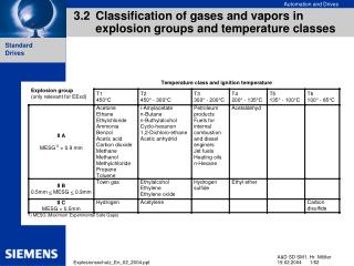
Apparatus Gas Groups • The flammable gases in which explosion protected electrical equipment may have to operate are grouped according to the amount of electrical energy, in the form of an arc, which is needed to ignite the gas.
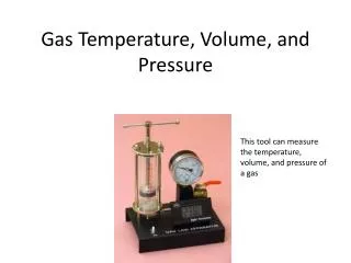
Temperature Class • This defines the maximum surface temperature of the components in the electrical equipment under normal and fault conditions. This maximum surface temperature must not exceed the gas ignition temperature. • The temperature class is stated with reference to a maximum ambient temperature of 40° C, should any other reference temperature be adopted, regulations require that this temperature be shown on the equipment.
It is important to note that the apparatus gas grouping and temperature class are not related. For instance, hydrogen requires very little spark energy to ignite, but the surface temperature necessary for ignition is very high (560 °C). • The following table relates the temperature class to the maximum surface temperature under fault conditions.
Temperature Class / Maximum surface temperature • T1 450 °C • T2 300 °C • T3 200 °C • T4 135 °C • T5 100° C • T6 85° C • For example, an electric motor may have a maximum surface temperature of 120 °C and would be classed as T4.
Types of Explosion Protection • There are a number of different constructional techniques employed in preventing electrical equipment causing explosions in hazardous areas. Some techniques, such as flameproof enclosures, have long been established but others, such as intrinsic safety and increased safety, are the result of developments in material and electrical/electronic circuit design. • It has been internationally agreed that explosion protected equipment be identified by the symbol "Ex" followed by a letter indicating the type of protection employed.
The following table lists the types of protection: SymbolType of Protection • Exdflameproof enclosure • Exiintrinsic safety • Exeincreased safety • Exnnon-sparking • Exqpowder filled (not applicable to ships) • Exooil immersed (not applicable to ships) • Exppressurisation • Exsspecial protection
Some equipment may use more than one of these types of protection in its construction. In this case, the primary type of protection is quoted first. For example, an increased safety motor with a flameproof terminal box would be marked Exe d. Equipment may also be marked with a prefix "E" which denotes compliance with European Standards e.g. EExe d.
Exd Flameproof Enclosure • Type 'd' protection, code EExd, uses a flameproof enclosure to contain the electrical apparatus. The internal apparatus may include parts which arcand surfaces which become hot. Gas may be inside the enclosure so it must fulfill three conditions: 1) The enclosure must prevent the flame and hot gases from being transmitted to the external flammable atmosphere. 2) The external surface temperature of the enclosure must remain below the ignition temperature of the surrounding gas under all operating conditions.
3) The transmission of flame and hot gases from a flameproof enclosure is prevented because all joints, such as flanges, shafts and bearings are closely machined to achieve a small gap which is less than a defined maximum. The pressure of an internal explosion is then released through the small gap between machined faces which cools the gas sufficiently to prevent it from igniting any external flammable atmosphere. • The maximum permitted gap depends upon three factors: 1) The type of gas with which the apparatus is safe for use. This is indicated by Apparatus Group. 2) The width of the joint (L). 3) The volume of the enclosure (V).
Exi Intrinsic Safety • These are circuits in which no spark nor any thermal effect produced under prescribed test conditions (which include normal operation and specified fault conditions) is capable of causing ignition of a given explosive atmosphere. Generally, this means limiting the circuit conditions to less than 30 V and 50 mA. Naturally, this restricts the use of Exi' protection to low power instrumentation, alarm and communication circuits. • The design of the circuit will depend on the type of gas present (gas grouping). • In the UK, two grades of intrinsic safety are recognised based on the safety factor of the equipment involved: • # Exia the highest category based on a safety factor of 1.5 with two faults on the circuit. • # Exib based on a safety factor of 1.5 with one fault on the circuit.
In addition to apparatus in the hazardous area being rated as intrinsically safe, an electrical safety barrier may also be fitted to the circuit. • The purpose of such a barrier is to limit voltages and currents in the hazardous area when faults occur on the circuit. • A separate barrier is required for each Exi circuit and they must be fitted outside the hazardous area.
A safety (or zener) barrier comprises: 1) A fuse to limit the maximum current through the shunt (zener) diodes. 2) A set of resistors to limit the maximum current into the hazardous area. 3) A set of shunt connected zener diodes to limit the maximum voltage appearing on the circuit within the hazardous area. 4) All components are sealed into a compact package with clearly marked terminals at each end of the barrier.
In the event of a short-circuit on the hazardous area wiring or equipment, the in-line resistors within the barrier will limit the size of fault current while the fuse blows. Two or three zener-resistor combinations are used within a barrier to provide back-up voltage anchors while the fuse is blowing. • After clearing a fault, the complete zener barrier must be replaced with an identical unit. No alterations to the original is allowed — remember this is a certified Ex safety device.
Cables for intrinsically safe circuits aboard ships should be separated from power cables and the crossing over of such cables should be at 90°. This is to minimise electromagnetic interference from the power cables affecting the intrinsically safe circuits. • The metallic cable screens of intrinsically safe circuits should be earthed at the power supply end only to prevent circulating currents within the sheath. • Power and intrinsically safe cable runs should be separately identified, i.e. by labels or by using cables with a distinctive colour (typically blue for Exi). (Adapted from:D.T. Hall:Practical Marine Electrical Knowledge)