Download
1 / 62
630 likes | 767 Views
Lecture 8: Digital Modulation II. Chapter 5 – Modulation Techniques for Mobile Radio. Recall our picture of the overall wireless transmission and receiving system:. Last lecture Analog AM and FM Benefits of Digital Modulation Power and Bandwidth Efficiencies

E N D
Lecture 8: Digital Modulation II Chapter 5 – Modulation Techniques for Mobile Radio
Recall our picture of the overall wireless transmission and receiving system:
Last lecture • Analog AM and FM • Benefits of Digital Modulation • Power and Bandwidth Efficiencies • Linear Modulation – BPSK, DPSK, QPSK • Bit error rate computations.
Constant Envelope Modulation Methods • Constant Envelope as compared to AM • Linear: Amplitude of the signal varies according to the message signal. • Constant Envelope: The amplitude of the carrier is constant, regardless of the variation in the message signal. It is the phase that changes.
Benefits of Constant Envelope • Power efficient • low out-of-band radiation of the order of -60dB to -70 dB • Simpler receiver design can be used. • High immunity against random FM noise and Rayleigh fading. • Disadvantage of Constant Envelope • Occupies larger bandwidth than linear modulation.
In the figure above, MSK is a type constant envelope modulation. • MSK has lower sidelobes than QPSK → –23 dB vs. –10 dB • MSK has larger null-to-null BW than QPSK → 1.5 Rbvs. 1.0 Rb • But 99% RF BW is much better than QPSK (1.2 Rbvs. 8.0 Rb!!) • very low ACI
Research • When responding to natural or man-made emergencies, cellular systems are heavily congested. • And users cannot be expected to regulate their behavior to allow emergency workers to use the spectrum. • Example heard from a radio report: A press person talked about how hard it was to make a phone call on September 11, 2001, but never mentioned that maybe their own need to communicate of a lower priority. • Press people have also been known to overload 9-1-1 call centers to try to get information for their reports.
GSM has a mechanism for identifying priority calls and queueing those calls if they are not first accepted. • Called the Wireless Priority Service (WPS). • This gives a lower blocking probability for those calls. • But this still does not alleviate congestion. • GSM uses a constant envelope modulation scheme (discussed below) that is not bandwidth efficient.
proposal: • Assume that after a disaster, the FCC might relax power restrictions. This would remove some of the expectation for the power efficiency for which GSM was designed. • Allow users to switch to a linear modulation scheme – to be more bandwidth efficient, needing less bandwidth to be used per channel, creating more channels. • But linear modulation also has more out-of-band ACI problems, so we must compensate for that.
Software-defined radios can be used to change modulation schemes on demand in software when a disaster occurs. • A part of the spectrum is set aside for the new modulation scheme. • And existing phones could still use standard GSM using another part of the spectrum. • Research: Finding a good linear modulation scheme, reducing ACI, and implementing the software defined radio.
BFSK • BFSK → Binary Frequency Shift Keying • Frequency of constant amplitude carrier shifted between two possible frequencies → fH= “1” and fL= “0” • ∆f = frequency offset from fc
BFSK signal • Can use a simple method to switch between two oscillators • but this might cause discontinuities • if the switching between signals is done when either one is not at a zero value • What problems do discontinuities cause?
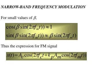
But the phase between bits can be made to be continuous • no discontinuity → constant envelope retained • if we design the circuits based on the definition of FM from before: • Then even if the message signal m (η) is discontinuous, the integral of it will not be and the signal will then be continuous. • But this is more complicated than simply switching between two oscillators.
BFSK BW • If B = baseband BW of the message signal • RF BW = 2 ∆f + 2 B • Assume that first null BW is used, the BW of rectangular pulses is B=R • RF BW = 2 ∆f + 2 R • BER for Coherent detection of BFSK
MSK • MSK → Minimum Shift Keying • Specific type of continuous phase (CP) FSK • Special condition: Peak frequency deviation is ¼ of the bit rate, so ∆f = 0.25 Rb • This is a smaller frequency separation (half that of conventional FSK) and has easier detection. • It possesses properties such as: • constant envelope • spectral efficiency • good BER performance • self-synchronizing capability.
An MSK signal can be thought of as a special form of OQPSK where the baseband rectangular pulses are replaced with half-sinusoidal pulses during a period of 2T
can be deduced that • MSK has a constant amplitude. • Phase continuity at the bit transition periods is ensured by choosing the carrier frequency to be an integral multiple of one fourth the bit rate, 1/4T. • the MSK signal is an FSK signal with binary signaling frequencies of fc + 1/4T and fc - 1/4T.
MSK RF signal BW • MSK has lower sidelobes than QPSK → –23 dB vs. –10 dB • MSK has larger null-to-null BW than QPSK → 1.5 Rbvs. 1.0 Rb • But 99% RF BW is much better than QPSK (1.2 Rbvs. 8.0 Rb!!) − very low ACI • Very popular modulation scheme for mobile radio
GMSK • GMSK → Gaussian MSK • The spectral efficiency of MSK is further enhanced by filtering the baseband signal of square pulses with a Gaussian filter.
Further reduces sidelobes. • Designed based on the product of the filter bandwidth (Bb) and the symbol period (T) • Bb T = ∞ corresponds to MSK • GSM uses Bb T = 0.3, which defines the bandwidth of the Gaussian filter • The smaller the value of Bb T, however, the higher the error rates. • Sacrifices the irreducible error rate in exchange for extremely good spectral efficiency and constant envelop properties
Summary: OQPSK (IS-95) and GMSK (GSM) are the two main modulation methods for 2G systems.
Combined Linear and Constant Envelope Modulation Techniques • We can allow both the phase and the amplitude to change at the same time – this would be a combination of linear and constant envelop methods. • We can extend the idea of QPSK to create symbols with M possible states (instead of just 2 or 4). • M = 2nso each symbol encompasses n bits of data.
M-ary PSK • M-ary PSK - constant envelope with more phase possibilities
the first null bandwidth of M-ary PSK signals decrease as M increases while Rb is held constant.
for fixed Rb , B ↓ and ηb ↑ as M ↑. • At the same time, M ↑ implies that the constellation is more densely packed, and hence the power efficiency ηp (noise tolerance) ↓.
QAM • Quadrature Amplitude Modulation (QAM) – Change both amplitude and phase. • The general form of an M-ary QAM signal
Basic tradeoff: Better bandwidth efficiency at the expense of power efficiency • More bits per symbol time → better use of constrained bandwidth • Need much more power to keep constellation points far enough apart for acceptable bit error rates. • need a large circle for M-ary PSK • symbols at corners (extreme points) of QAM constellation use a lot of power.
M-ary FSK • M-ary FSK • Frequencies are chosen in a special way so that they are easily separated at the demodulator (orthogonality principle). • M-ary FSK transmitted signals: • fc = nc / 2Ts for some integer nc • The M transmitted signals are of equal energy and equal duration • The signal frequencies are separated by 1/ 2Ts Hz, making the signals orthogonal to one another
The bandwidth efficiency of an M-ary FSK signal ↓ with M↑ • Power efficiency ↑ with M↑ • Since M signals are orthogonal, there is no crowding in the signal space
Spread Spectrum Modulation (SSM) • Tx expands (spreads) signal BW many times with a special code and the signal is then collapsed (despread) in Rx with the same code • Other signals created with other codes just appear at the Rx as random noise. • Trade BW for signal power like with FM
Advantages 1) Resistant to narrowband interference – interference can only realistically affect part of the signal. 2) Allows multiple users with different codes to share same the MRC • no frequency reuse needed • rejects interference from other users
Combats multipath fading → if a multipath signal is received with enough delay (more than one chip duration), it also appears like noise. 4) Can even use shifted versions of codes to isolate and receive different multipath components (RAKE receiver which we will see later) 5) As # simultaneous users ↑ the bandwidth efficiency↑
Signal spreading is done by multiplying the data signal by a pseudo-noise (PN) code or sequence • the pseudo-noise signal looks like noise to all except those who know how to recreate the sequence.
PN Codes • Binary sequence with random properties → noise-like (called "pseudo-noise" because they technically are not noise) • ≈ equal #’s of 1’s and 0’s • Very low correlation between time-shifted versions of same sequence
Very low cross-correlation between different codes • each user assigned unique code that is approximately orthogonal to all other codes • the other users’ signals appear like random noise!
Exactly 2m-1 nonzero states for an m-stage feedback shift register • The period of a PN sequence can not exceed 2m-1 symbols (maximal length)
Spreading codes • The correlation properties of PN codes are such that this slight delay causes the multipath to appear uncorrelated with the intended signal • Multipath contributions appear invisible the desired Rx signal
Direct Sequence (DS) • Two types of SSM – DS & FH 1) Direct Sequence (DS) • Multiply baseband data by PN code (same as diagram above) • Spread the baseband spectrum over a wide range. • The Rx spread spectrum signal • m(t) : the data sequence • p(t): The PN sequence
Frequency Hopping (FH) 2) Frequency Hopping (FH) • Randomly change fcwith time • Spread the frequency values that are used over a wide range. • In effect, this signal stays narrowband but moves around a lot to use a wide band of frequencies over time.
Hopset : the set of possible carrier frequencies • Hop duration: the time during between hops • Classified as fast FH or slow FH • fast FH: more than one frequency hop during each Tx symbol • slow FH : one or more symbol are Tx in the time interval between frequency hops.