Download
1 / 51
510 likes | 631 Views
Lightweight Hierarchical Error Control Codes for Multi-Bit Differential Channels. Jason D. Bakos Ph.D. Proposal. …. Raw data stream. …. …. …. …. blocks. k. k. k. …. …. …. …. code blocks. n. n. n. Introduction. New type of error control code

E N D
Lightweight Hierarchical Error Control Codes for Multi-Bit Differential Channels Jason D. Bakos Ph.D. Proposal
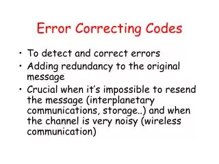
… Raw data stream … … … … blocks k k k … … … … code blocks n n n Introduction • New type of error control code • Operate over existing channel encoding mechanism • Lightweight • Requires less code overhead relative to traditional ECC codes • Exploit inherent properties of underlying channel code • Traditional ECC codes:
Talk Outline • Motivation • High-speed signaling technology • Multi-Bit Differential Signaling (MBDS) • Characteristics of the nCm channel code • Approach • Hierarchical Encoding for Error Control • Computing code rate of LHECC codes • Encoding/decoding examples • Analysis of LHECC codes • Sample decoder architecture • Experimental results • Simulation setup • Simulation results • Future Work
Talk Outline • Motivation • High-speed signaling technology • Multi-Bit Differential Signaling (MBDS) • Characteristics of the nCm channel code • Approach • Hierarchical Encoding for Error Control • Computing code rate of LHECC codes • Encoding/decoding examples • Analysis of LHECC codes • Sample decoder architecture • Experimental results • Simulation setup • Simulation results • Future Work
Motivation • High performance electrical chip-to-chip signaling chip 2 PCB traces PCB traces chip 3 chip 1 • Processor-Memory interconnect • Other chip-to-chip interconnect • High-resolution digital displays • Storage devices • High-speed sensors
Source: Intel Corporation Need for High-Speed Off-Chip Signaling • Growing gap between on-chip signaling speed and off-chip signaling speed
Packaged chip Packaged chip PCB trace Ground plane Challenges for Off-Chip Signaling • High-speed links must be narrow • I/O pads are a precious resource in chip design • High-speed drivers are large due to skin effect • Integrity of high-speed off-chip signals • capacitance, inductance • additional noise • synchronization / timing • Solution: • Couple data encoding to circuit design • Increase signal integrity • Recover from signal errors
Multi-Bit Differential Signaling (MBDS) • Differential signaling (LVDS) • MBDS • Data encoded as • {01} or {10} • Advantages • Low switching noise • No reference noise • Coupled transmission lines • Low noise => low voltage swing • Disadvantages • Two connections for each bit • Wasteful in I/O pads • Data encoded with fixed number of ones • N-choose-M (nCm) • {0011}, {0101}, {0110}, {1001}, {1010}, {1100} • Advantages • Same noise rejection as differential • Higher information capacity
nCm Coding EXAMPLE 6-wire MBDS channel code size = 20 codes effective bits = 4 equivalent to 8-wire differential channel 25% fewer pads (8 versus 6) 25% less power (4 1-bits on versus 3) 125% code capacity (20 codes versus 16) Code set size Effective bits
Properties of nCm Code Sets • Inherent error detecting ability • Receivers can detect invalid code words • Extra code words • For mapping code words to binary values
Odd-number of bit errors 1011 1101 0111 1110 0011 0001 1000 0010 0100 1 error 3 errors • Even-number of bit errors 0011 1111 1001 2 errors 1001 1010 0101 0110 0000 nCm Codes: Inherent Error Detection • Most types of bit errors result in invalid code words • Word is invalid if unequal number of 1 and 0 bits are flipped
bits flipped in code word 6c3 code word error vectors error vector result nCm Codes: Even Number of Bit Errors • What is the probability of detecting an even number of bit errors? • Example: • 6c3 • 2 errors • Assume q errors (q is even) • Create error vector that indicates which bits are flipped
error vectors for 1-bits error vectors for 0-bits Example: 6c3 with 2 bit errors Probability for detecting q errors error vectors that yield valid code word * nCm Codes: Even Number of Bit Errors • For errors resulting in valid code words • q errors • assume separate error vectors for 1-bits and 0-bits • size error vector for 1-bits: m • size of error error for 0-bits: n-m
0011 00 0101 01 0110 10 1001 11 1010 ? 1100 ? • Exploit by using 2 MBDS channels in parallel as bus 6 cw 6 cw 36 combinations 5 bits 4c2 4c2 2 bits 2 bits nCm Codes: Extra Code Words • Each nCm code set has unmapped code words • Use to offset overhead for error control 4c2 code set => binary value
Exploiting Extra Code Words • Fractional bits = • log2(cw) – floor(log2(cw)) • Therefore, need 1 / (fractional bits) channels in parallel to gain additional bit • Example: • 6c3 => 20 cw => log2(20) = 4.3219 bits • ceiling(1 / .3219) = 4 channels 24.3 24.3 24.3 24.3 * * * 6c3 6c3 6c3 6c3 .3 + .3 + .3 + .3 = 1.2 additional bits
Talk Outline • Motivation • High-speed signaling technology • Multi-Bit Differential Signaling (MBDS) • Characteristics of the nCm channel code • Approach • Hierarchical Encoding for Error Control • Computing code rate of LHECC codes • Encoding/decoding examples • Analysis of LHECC codes • Sample decoder architecture • Experimental results • Simulation setup • Simulation results • Future Work
Approach • Need to build error control code: • Works over nCm code set • Takes advantage of nCm properties
Start with block of binary data raw binary data Encode portion of data into symbolic ECC block Sets rules for nCm selection Symbolic ECC block Higher-Level Code Encode remainder of data by choosing valid nCm codes governed by rules set by symbolic block Lower-Level Code nCm block Hierarchical Encoding for ECC
Example: 4c2, distance=4 1100 0101 0011 0110 1001 1010 Lower-Level: Partitioning nCm Code Sets • nCm code sets have distance=2 • Not enough for bit correction, t = floor((d-1) / 2) • Increase distance by partitioning into “distance subsets” • Subsets: • 0 => {0011, 1100} • 1 => {0101, 1010} • 2 => {0110, 1001} • IDEA: If the subset is known, bit errors may be corrected
Partitioning Problem • Partitioning operation is not trivial • Graph coloring is too complex for large code sets ( > 6c3) • Good news: • Done off-line • Won’t go beyond 8c4 code set • Use heuristic… • Based on pruning depth-first search over space of code word subset assignment
minimize subsets for higher code rate minimize cw/subset for higher ECC nCm Partitionings Trade-off between code rate and ECC
Example Partitioning • Example partitioning • 7c3 code set • 7 groups (subsets) • 5 code words per subset • distance=4
k data symbols n-k parity symbols block size=n Upper Level: Linear Block Codes • Can correct: • erasures • errors • Checksum • Requires 1 parity symbol • Can correct 1 erasure • MDS code (Reed-Solomon) • Can correct erasures: • Number of parity symbols • Can correct errors: • Number of parity symbols / 2 • Restrictions: • Symbol base must be prime or power of a prime • Max block size = symbol base + 1 • Near-MDS code • Can correct erasures: • Number of parity symbols - 1 • Can correct subset errors: • (Number of parity symbols – 1) / 2 • Restrictions: • Symbol base must be prime or power of a prime • If symbol base = pm • Max block size = pm+1 - 1
(c-data) (s-data) 0101001001 0010010100 base conv. 2->s base conv. 2->c Data symbols Parity symbols Data as code words Parity as code words Encoding Hierarchical Block Codes b bits 01010010010010010100
Computing Code Rate for LHECC • Code rate • Defines information capacity vs. bits • code rate = number of data bits / total code word bits (wires) • Block code parameters (n,k) • Partition parameters (s,c) • High level (s-data) • sk total values • Low level (c-data) • cn total values • We “break even” when code rate matches differential at 50%
Encode 111101… 1112 = 213 2 1 • Compute checksum parity… 2 1 0 • Encode 101… 1 0 1 bit grp. 2 1 0 Example #1: Encoding • Assume 3 x 4c2 channels • Low level => s=3, c=2 • (3,2) checksum code • s-data • sk = 9 cw (3 bits) • c-data • cn = 8 cw (3 bits) • code rate = 6 bits / 12 channels = 50% • “Free” ECC • Can correct one bit error within 1 code word 1001 0101 1100
grp. 2 1 0 ? 1 0 cw 1001 0101 1100 1101 0101 1100 Example #1: Decoding • Decoder: • If invalid code word is detected • Determine subset of code word in error • Use minimum distance decoder to determine correct codeword • Assume bit error occurs… • 0 – 1 = 2 (mod 3) • Symbol in error must be 0110 or 1001 • dist(1101,0110) = 3, dist(1101,1001) = 1 • Corrected symbol is 1001
Example #2: Encoding • Need MDS generator matrix for encoding • G = [ Ik Ak x (n-k) ] • Assume 4 x 4c2 channels • s=3, c=2 • (4,2) MDS code • s-data • sk = 9 cw (3 bits) • c-data • cn = 16 cw (4 bits) • code rate = 7 bits / 16 channels = 44% • Can correct one bit error in two code words • Need MDS parity-check matrix for decoding • H = [ -AT In-k]
2 0 100 1 1 • Encode 1010... 1 0 1 0 bit 1 1 grp. 2 0 Example #2: Encoding • Encode 1001010… 1010 0101 1001 0011
1110 0101 1001 0001 1010 0101 1001 0011 grp. 1 1 2 0 grp. ? 1 2 ? 1 0 dist(0001,0011)=1 dist(0001,1100)=3 dist(1110,0101)=3 dist(1110,1010)=1 1010 0101 1001 0011 grp. 1 1 2 0 bit 1 0 1 0 (recover c-data) Example 2: Erasure Decoding 0 => {0011, 1100} 1 => {0101, 1010} 2 => {0110, 1001} 2 erasures! (recover s-data) 113 = 1002
0110 0101 1001 0011 1010 0101 1001 0011 grp. 2 1 2 0 grp. 1 1 2 0 Example 2: Error Decoding 0 => {0011, 1100} 1 => {0101, 1010} 2 => {0110, 1001} no error dist(0110,0101)=2 dist(0110,1010)=2 • Can’t correct nCm code word without partitioning for more distance • Can decode s-data
010110 110010 100101 001011 grp. 6 2 8 1 010110 110010 101001 001011 grp. 6 2 6 1 Example 3: Multiple Bit Error Correction • 4 x 6c3 channels • 9 subsets, 2 cw/subset, distance=6 • Assume (4,2,9) MDS code • Code rate • =[log2(81)+log2(16)]/24=10/24=42% dist(101001,011010)=4 dist(101001,100101)=2 corrected code word is 100101
Analysis of Checksum-Based Codes • LHECC codes defined as • nCm code set • (s,c,d) • (n,k,d) • Fully utilized partitioning • s*c = cw • 1/1 correction code rate # wires original code rates 4c2 => 2/4 = 50% 5c2 => 3/5 = 60% 7c3 => 5/7 = 71% 8c4 => 6/8 = 75%
Analysis of Checksum-Based Codes • Under-utilized partitionings • s * c < cw code rate original code rates 6c3 => 4/6 = 66% 7c3 => 5/7 = 71% 8c4 => 6/8 = 75% # wires
Analysis of Multiple Bit-Correcting Codes • 5c2, 7c3 • 2 parity symbols used • MDS-code used until reached limit • After MDS limit, NMDS code used • 6c3 • Code set distance is 6 (t=2) • One parity symbol • 8c4 • Code set distance is 8 (t=3) • One parity symbol code rate # wires
non-binary MDS decoder (need good block MDS codes) cw resolvers RS decoder grp. values lookup cw selection lookup cw fixers fixes code word based on recv’d code word and group value cw resolvers: determine s/c data from nCm code word (make simpler with good partitioning) base translation lookup tables Example Implementation Example (8,6) symbol decoder binary output MBDS receiver input color legend: nCm code words s-values c-values
Talk Outline • Motivation • High-speed signaling technology • Multi-Bit Differential Signaling (MBDS) • Characteristics of the nCm channel code • Approach • Hierarchical Encoding for Error Control • Computing code rate of LHECC codes • Encoding/decoding examples • Analysis of LHECC codes • Sample decoder architecture • Experimental results • Simulation setup • Simulation results • Future Work
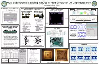
Simulation Setup • Provide realistic simulation setup • Simulate sources of errors • Transmission line low-pass filtering • Common-mode noise • Jitter
Simulation Testbench • PCB transmission line model • Lumped LC model • 4-way coupled • Matched to 50 ohm characteristic impedance • Match termination network
Sample voltages relative to common here random valid nCm code words (CMOS digital) CMOS code words out solder bump model solder bump model wire bond model Simulation Testbench
Experiment #1: Eye Plots • Transmission lines cause signal degredation at high speeds • Filters out high frequencies • 4c2 channel at 500 Mb/s 500 bit times • 4c2 channel at 1.6 Gb/s 500 bit times
Inject AWGN(0,1)*0.04 into each wire 1.6 Gbps 1300 ps latency Experiment #2: Common-Mode Noise
Experiment 2: Common-Mode Noise • Code word in error if any bits are in error • Simulation run for 10,000 bit times • (cw_correctno_noise – cw_correctnoise) / total_codewords • Ran simulation for 1.25 Gbps and 1.60 Gbps
Optimal latency (jitter margin) 1.25 Gb/s Infrequent bit errors occur 1.6 Gb/s Experiment 3: Code Word Bit Error Rates • Bit error rates for 1.25 Gb/s and 1.6 Gb/s
Talk Outline • Motivation • High-speed signaling technology • Multi-Bit Differential Signaling (MBDS) • Characteristics of the nCm channel code • Approach • Hierarchical Encoding for Error Control • Computing code rate of LHECC codes • Encoding/decoding examples • Analysis of LHECC codes • Sample decoder architecture • Experimental results • Simulation setup • Simulation results • Future Work
Future Work • Show that LHECC codes are optimal for MBDS channels • MDS codes optimal for symbolic codes • Show that LHECC codes make the best use of nCm properties to absorb ECC penalty
LHECC encoding/decoding logic should fit into reasonable space and operate at I/O speed 4 x 4c2 MBDS drivers 4 x 4c2 MBDS receivers Future Work • Design efficient implementation
Future Work • Design accurate simulation environment with LHECC logic to show effectiveness of LHECC codes • Add accurate error sources • Circuits • Transmission lines