Download
1 / 52
520 likes | 724 Views
Lightweight Hierarchical Error Control Codes for Multi-Bit Differential Channels. Jason D. Bakos Ph.D. Committee: Donald M. Chiarulli Steven P. Levitan Bruce R. Childers Patchrawat Uthaisombut. Introduction. New class of error control codes “Lightweight Hierarchical Error Control Codes”

E N D
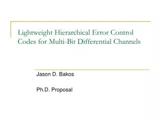
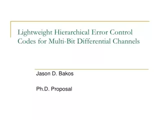
Lightweight Hierarchical Error Control Codes for Multi-Bit Differential Channels Jason D. Bakos Ph.D. Committee: Donald M. Chiarulli Steven P. Levitan Bruce R. Childers Patchrawat Uthaisombut
Introduction • New class of error control codes • “Lightweight Hierarchical Error Control Codes” • Applicable to system-level interconnect • Operates over new high-performance system-level interconnect technology • “Multi-Bit Differential Signaling (MBDS)” • Uses inherent properties of MBDS to achieve error control while requiring minimal data and logic overhead
System-Level Interconnect • Network-on-chip • Multi-Chip Modules • System-level interconnect • Short-haul • High-speed • Printed circuit boards • Backplanes • Peripherals
Packaged chip Packaged chip Source: Intel Corporation Challenges for System-Level Interconnect • Signal integrity • Capacitance, inductance • Noise, crosstalk • Synchronization/jitter • Area • I/O pads precious • Driver size
Error Control Codes • Error control codes used to increase signal integrity over noisy channels • Examples: • Cellular networks, deep-space signaling, digital TV transmission, hard/optical disks • Low-speed channels • ECC codes require information overhead • Acceptable for low-speed channels • Minimize by applying code over large blocks of data • Example: • 187 bytes for HDTV
Error Control Codes • ECC over large blocks requires complex decoding • Memory, latency • Encoding/decoding logic complexity • Encoding/decoding performed using software or dedicated ASICs • Performed at Mb/s-speeds • Traditional ECC codes not practical for system-level interconnect • Encode/decode in small area • High-throughput (core speed) • Need new class of ECC code for system-level interconnect • Small block size • Low overhead
Talk Outline • Multi-Bit Differential Signaling (MBDS) • “N choose M” data encoding • Lightweight Hierarchical Error Control Codes (LHECC) • Encoder/decoder implementation • Experimental verification • Link modeling • Noise modeling • Experimental results • Conclusion
Multi-Bit Differential Signaling (MBDS) • Differential (LVDS) channels • Multi-Bit Differential (MBDS) channel • Current-mode drivers • Data encoded as • {01} or {10} • Advantages • Low switching noise • Large GDP • Common-mode noise rejection • EM coupled transmission lines • Low noise => low voltage swing • Disadvantages • Wasteful in I/O pads • Scale up LVDS driver • Data encoded with fixed number of ones • “N-choose-M (nCm)” symbols • {0011}, {0101}, {0110}, {1001}, {1010}, {1100} • Advantages • Same transmission characteristics as differential • Higher information capacity
MBDS / “n choose m (nCm)” Encoding Symbol set size Effective bits • EXAMPLE • 6-wire MBDS channel • 20 symbols • effective bits = 4 • equivalent to 8-wire differential channel • 25% fewer pads (8 versus 6) • 25% less power (4 1-bits on versus 3)
4c2 symbols => binary value 0011 00 0101 01 0110 10 1001 11 1010 ? 1100 ? 6 sym 6 sym 36 combinations 5 bits 4c2 4c2 2 bits 2 bits nCm Encoding: Unused Symbol Space • Each nCm symbol set has unmapped symbols • Solution #1 • Use multiple MBDS channels in parallel • Solution #2 • Exclude symbols for purposes of ECC
nCm Encoding: Inherent Error Detection • Most types of symbol errors can be detected at receiver Odd-number of bit errors 1011 1101 0111 1110 0011 0001 1000 0010 0100 1 error 3 errors Even-number of bit errors 0011 1111 1001 2 errors 1010 0101 0110 0000
Talk Outline • Multi-Bit Differential Signaling (MBDS) • “N choose M” data encoding • Lightweight Hierarchical Error Control Codes (LHECC) • Encoder/decoder implementation • Experimental verification • Link modeling • Noise modeling • Experimental results • Conclusion
Hierarchical Encoding LHECC relies on a hierarchical approach to encoding Binary source data start with raw binary data c-data s-data Encode portion of data, set rules for nCm symbol selection high-level code Symbolic ECC block Code word over parallel MBDS channels Encode remainder of data using nCm symbols low-level code
1100 0101 0011 0110 1001 1010 Low-Level Code • nCm symbol sets have Hamming distance (d) = 2 • Correctable bits = floor((d-1)/2) • Set new distance by partitioning into equal-size subsets • s subsets, c symbols/subset • Subsets: • 0 => {0011, 1100} • 1 => {0101, 1010} • 2 => {0110, 1001} • If subset is known, bit errors may be corrected • Example: 0111, subset=2 • Correct to 0110 • Performed off-line Example: 4c2, distance=4
0: 1: 2: 3: 0: 1: 2: 3: 0: 1: 2: 3: 0: 1: 2: 3: Partitioning Operation • Perform search over space of assignments • Must know: distance, # subsets (s), and symbols/subset (c) • Minimize s while maximizing c Example: 6c3, 4/4, distance=4 subset 0: subset 1: 000111 001011 001101 Result: Each nCm symbol becomes associated with an s-data component and a c-data component Example: 100101 s-data: 1 c-data: 2 000111 011100 101010 110001 001011 010110 100101 111000 001110 010011 010101 010110 011001 011010 011100 subset 2: subset 3: 100011 100101 100110 001101 011010 100011 110100 001110 010101 101001 110010 101001 101010 101100 110001 110010 110100 111000
Can correct: • erasures • errors k data symbols n-k parity symbols block size=n High-Level Code: Linear Block Codes • Checksum • Requires 1 parity symbol • Can correct 1 erasure • Near-MDS code • Corrects erasures: • Number of parity symbols - 1 • Corrects errors: • (Number of parity symbols – 1) / 2 • Restrictions: • Symbol base must be prime or power of a prime • If symbol base = pm, max block size = pm+1 - 1 • MDS code (Reed-Solomon) • Can correct erasures within block: • Number of parity symbols • Can correct errors within block: • Number of parity symbols / 2 • Restrictions: • Symbol base must be prime or power of a prime • Max block size = symbol base + 1
b bits (c-data) (s-data) 01010010010010010100 0101001001 0010010100 base conv. 2->s Parity symbols base conv. 2->c Data as nCm symbols Parity as nCm symbols Data symbols Encoding LHECC
Code Rate and Overhead • LHECC codes are defined as (nCm,n,k,dh,s,c,dl) codes • High-level code: k*log2(s) bits • Low-level code: n*log2(c) bits • Advantages over traditional block ECC: • Requires less number of parity symbols for correction • Parity symbols carry data
Encode 111101… 1112 = 213 2 1 • Compute checksum parity… 2 1 0 • Encode 101… 1 0 1 bit sub. 2 1 0 Example #1: Encoding • Assume 3 x 4c2 channels • Low level • s=3, c=2 • High level • (3,2) checksum code • s-data • 32 = 9 cw (3 bits) • c-data • 23 = 8 cw (3 bits) • 6 bits / 12 wires • rel=1.0, abs=0.5, oh=0 • Can correct one bit error within 1 symbol 1001 0101 1100
sub. 2 1 0 ? 1 0 sym 1001 0101 1100 1101 0101 1100 Example #1: Decoding • Decoder: • If invalid code word is detected • Determine subset • Use minimum distance decoder • Assume bit error occurs… • 0 – 1 = 2 (mod 3) • Symbol in error must be 0110 or 1001 • dist(1101,0110) = 3, dist(1101,1001) = 1 • Corrected symbol is 1001
Example #2: Encoding • Assume 4 x 4c2 channels • s=3, c=2 • (4,2) MDS code • s-data • 32 = 9 symbols (3 bits) • c-data • 24 = 16 symbols (4 bits) • 7 bits / 16 wires • rel=7/8=.88, abs=.44, oh=1 bit • Can correct one bit error in two symbols • Need MDS generator matrix for encoding • G = [ Ik Ak x (n-k) ] • Need MDS parity-check matrix for decoding • H = [ -AT In-k]
2 0 100 1 1 • Encode 1010... 1 0 1 0 bit 1 1 sub. 2 0 Example #2: Encoding • Encode 1001010… 1010 0101 1001 0011
1110 0101 1001 0001 1010 0101 1001 0011 sub. 1 1 2 0 sub. ? 1 2 ? 1 0 dist(0001,0011)=1 dist(0001,1100)=3 dist(1110,0101)=3 dist(1110,1010)=1 1010 0101 1001 0011 grp. 1 1 2 0 bit 1 0 1 0 (recover c-data) Example 2: Erasure Decoding 0 => {0011, 1100} 1 => {0101, 1010} 2 => {0110, 1001} (recover s-data) 113 = 1002
0110 0101 1001 0011 1010 0101 1001 0011 sub. 2 1 2 0 sub. 1 1 2 0 Example 2: Error Decoding 0 => {0011, 1100} 1 => {0101, 1010} 2 => {0110, 1001} no error dist(0110,0101)=2 dist(0110,1010)=2 • Can’t correct nCm symbol without partitioning for more distance
010110 110010 100101 001011 sub. 6 2 8 1 010110 110010 101001 001011 sub. 6 2 6 1 Example 3: Multiple Bit Error Correction • 4 x 6c3 channels • 9 subsets, 2 sym/subset, distance=6 • Assume (4,2,3) MDS code • rel=10/16=.63, abs=10/24=42% dist(101001,011010)=4 dist(101001,100101)=2 corrected symbol is 100101
Hamming displacement=4 0101 0101 1010 Hamming displacement=2 Hamming displacement=2 0101 0011 1001 LHECC Theory • LHECC is equivalent to binary code space over MBDS channels • Example: LHECC-encoded code word • high-level distance=2 • low-level distance=4 • Assume inter-subset distance=2 s-data: 111, c-data: 110 0101 0101 0101 s-data: 111, c-data: 111 s-data: 101, c-data: 110
Talk Outline • Multi-Bit Differential Signaling (MBDS) • “N choose M” data encoding • Lightweight Hierarchical Error Control Codes (LHECC) • Encoder/decoder implementation • Experimental verification • Link modeling • Noise modeling • Experimental results • Conclusion
Encoder/Decoder Implementation • Responsible for binary-to-nCm conversion as well as error detection/correction • Encoders/decoders should be small • Should operate at core speed • Hierarchical encoding/decoding lends itself to pipelined implementation • Synthesized using standard cell library • Latch, inverter, 2/3-input NAND, 2/3-input NOR • Example interconnect organization: driver receiver driver encoder binary receiver decoder binary driver receiver
EACH: 63 gates 5 gate delays 19 gates 5 gate delays gen. cw sa(2) 6c3 (a) ca(2) s-data (4 bits) checksum checksum (2-bits) sb(2) gen. cw 6c3 (b) pipeline reg (12 bits) pipeline reg (18 bits) cb(2) ss(2) c-data (6 bits) gen. cw 6c3 (s) cs(2) 3x6c3 Encoder Implementation • Implement a 3x6c3 code (1 bit error in 1 symbol) • s-data is 2*log2(4) = 4 bits • c-data is 3*log2(4) = 6 bits • Carries 10 bits over 18 wires • Relative code rate = 10 / (3*4) = 83.3% • Absolute code rate = 10 / 18 = 55.6% Total: 208 gates, 30 latches High-level code Low-level code
3x6c3 Decoder Implementation 96 gates 6 gate delays err flags(3) err flags(3) err flags(3) err flags(3) Total: 830 gates, 128 latches nofix cwa(6) cw(6) cw(6) 84 gates 6 gate delays cwb(6) 118 gates 8 gate delays md_err cws(6) cerror 49 gates 7 gate delays xora (6) xora (6) c_error(2) corr_c(2) 6 gates 2 gate delays ea xorb (6) xorb (6) sa(2) md_decoder stage 2 md_decoder stage 1 s-data (4) xorc (6) resolver xorc (6) 6c3 ca(2) corr_s(2) corr_s(2) xord (6) xord (6) blk-corrector md_err pipeline reg (33 bits) pipeline reg (22 bits) pipeline reg (38 bits) pipeline reg (17 bits) eb s-data (4) pipeline reg (18 bits) sb(2) 16 gates 3 gate delays resolver 6c3 cb (2) blk_error detector nofix sa(2) sa(2) sa(2) ca(2) corr_s(2) corr_c(2) sb(2) sb(2) es sb(2) cb(2) corr_s(2) c-data (6) 6c3 corr_c(2) 47 gates 7 gate delays ss(2) resolver c-data(6) c-data(6) c-data(6) cs(2) cs (2) nofix nofix corr_c(2) 130x3 gates 7 gate delays 24 gates 3 gate delays High-level code Low-level code 1 Low-level code 2 Resolver Routing
Talk Outline • Multi-Bit Differential Signaling (MBDS) • “N choose M” data encoding • Lightweight Hierarchical Error Control Codes (LHECC) • Encoder/decoder implementation • Experimental verification • Link modeling • Noise modeling • Experimental results • Conclusion
Input is sampled at midpoint cwn Driver input cwn-1 cwn+1 Outputs sampled at t(input) + latency Receiver output cwn-1 cwn cwn+1 latency PCB Interconnect Model • Single MBDS channel CMOS code words out CMOS code words in • Replicated for each channel forming the interconnect
4c2 output 4c2 input Bias input Driver/Receiver Modeling MOSFET models from TSMC .18 um PDK Driver circuit Receiver circuit source: Stefan Hirsch, Hans-Jörg Pfleiderer, “CMOS receiver circuits for high-speed data transmission according to LVDS-standard,” Proceedings of SPIE Vol. 5117 (2003). Bias current = 7.5 mA mean-abs current per leg
solder bump model solder bump model wire bond model Package Modeling
PCB Transmission Line Modeling Length=7.5” 4c2 6c3 8c4 FR4 PCB material Individual t-lines matched to 50 ohms Width=16 mil, thickness=1.4 mil, distance=16 mil Layer spacing based on commercial PCB process • Fully coupled transmission line models • Ground capacitance, serial inductance • Coupled with mutual capacitance, mutual inductance
Noise Modeling • Goal: Capture link behavior in the presence of noise • Error sources from link model: • Transistors: jitter, switching noise • Transmission lines: frequency-dependant attenuation, crosstalk • Receivers discriminate signal to convert to digital Input to receiver 1.8 GCW/s 2.2 GCW/s 2.6 GCW/s 3.0 GCW/s 3.4 GCW/s 3.8 GCW/s 4.2 GCW/s 4.6 GCW/s Receiver output
Supply Noise • Intel: Busy 1.5 V Pentium 4 processor: • Stddev = 17-20 mV • Add independent Vdd noise to driver and receiver • To generate: • Assume links operating at core switching frequency • Generate white Gaussian noise • Sampled at 20 GHz for 20 us • Apply passband filter to noise, 200 MHz band centered on op. frequency Source: private correspondence with Martin Saint-Laurent, Intel Corporation
Fringe Capacitance in Driver • Fringe capacitance from circuit layouts and packaging add parasitic capacitance effects • Where it hurts channel most (noise source) • Adds additional crosstalk
Experimental Verification • Goal: measure amount of improvement in channel performance from the addition of LHECC support to MBDS links • Setup 5 interconnects with various capacities and levels of error control • Simulate interconnects with analog simulator • Test each link with a random sequence of 100,000 code words transmitted at several code word transmission rates • Measure error rates for each test at the output of receivers for links with and without LHECC support • Determine maximum transmission rate for code word error rate < 10-5
Experimental Interconnects • Correct 1 symbol containing 1 bit error • Correct 2 symbols containing 1 bit error • Correct 2 symbols containing 2 bit errors or 1 symbol containing 2 bits where errors yield valid nCm symbol
Talk Outline • Multi-Bit Differential Signaling (MBDS) • “N choose M” data encoding • Lightweight Hierarchical Error Control Codes (LHECC) • Encoder/decoder implementation • Experimental verification • Link modeling • Noise modeling • Experimental results • Conclusion
Experimental Results: Internal noise sources only (transistor noise, channel crosstalk)
Experimental Results (multi-symbol ECC) Internal noise sources only
Experimental Results (multi-symbol ECC) Supply noise characteristics added
Experimental Results (multi-symbol ECC) Crosstalk from fringe capacitance