Download
1 / 12
120 likes | 128 Views
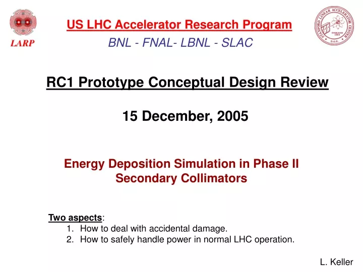
US LHC Accelerator Research Program. BNL - FNAL- LBNL - SLAC. RC1 Prototype Conceptual Design Review 15 December, 2005. Energy Deposition Simulation in Phase II Secondary Collimators. Two aspects : How to deal with accidental damage.

E N D
US LHC Accelerator Research Program BNL - FNAL- LBNL - SLAC RC1 Prototype Conceptual Design Review 15 December, 2005 Energy Deposition Simulation in Phase II Secondary Collimators • Two aspects: • How to deal with accidental damage. • How to safely handle power in normal LHC operation. L. Keller
Problem: A kicker failure can deposit 9 x 10¹¹ protons (8 bunches) on any metallic secondary collimator - causing it to melt within a substantial volume. Missteered beam 9E11 protons (8 bunches) on secondary Jaw 120 cm 3D ANSYS model, E. Doyle Cross section at shower max. Copper Jaw Copper 2.5 cm Fracture temp. of copper is about 200 deg C 2000 °C (not incl. heat of fusion)
SLAC Damage Test - 1971 Beam entering a few mm from the edge of a 30 cm long copper block The length and depth of this melted region is comparable to the ANSYS simulation for the LHC accident. 30 cm 500 kW e- beam Beam diameter ~ 2000 µ It took about 1.3 sec to melt thru the 30 cm block, but for this relatively large beam, the front two radiation lengths remain intact.
FLUKA-generated Simulation Model IR-7 dipoles Beam 2 Beam 1 First secondary collimator Primary collimators 40 m
Beam’s Eye View of a Phase I SkewSecondary Collimator stainless steel frame water “upper right” jaw, 8.0 cm parallel to gap, 2.5 cm perpendicular to gap TCSM1 So far, all FLUKA energy deposition simulations at SLAC have used this model for the primary and secondary collimators and varied the jaw material, length, and gap.
Energy Spectra of Particles Hitting TCSM1 Total energy of particles hitting both jaws is ≈ 3400 Gev/p seven s gap Keller: 2004-10-06
Power into the One Jaw of the First Secondary Collimator vs. Length More than 80% of the total power deposition is EM showers, mainly from π0 decays 4 x 10¹¹ p/s lost
Transverse Power Distributions in TCSM1 at Shower Maximum Power lost in a 5 cm longitudinal slice from halo interacting in 60 cm primary collimator, TCPH, total 6.8 kW
Comparing TCPV with TCPH, the main differences occur in the 1st three secondary colls. Data from COLLTRK Y. Cai 4 x 10¹¹ p/s lost
Power Deposition on First Secondary Collimator in 12 Min. Lifetime (kW per jaw, 120 cm long jaw) The most recent ANSYS simulations have been for this case. Reduce jaw length to 75 cm: 68 kW => 58.5 kW • Notes: • Ray files for 60 cm long carbon primary collimators from LHC Collimator web page, July 2005.
Next Steps for FLUKA and ANSYS (for completeness, in parallel with construction) • In the Phase II configuration with all 95 cm long copper cylinders, recalculate the energy absorbed by the down-beam superconducting magnets. In the CERN full-blown FLUKA model of IR7, must add secondary 95 cm, water-cooled, copper cylinders with 10 cm tapered ends and leave the Phase I carbon secondaries in place with their jaws withdrawn. Need help from the CERN group for this work. • In the “short” FLUKA model change the first secondary collimator to a 95 cm water-cooled cylinder with tapered ends and include the water channels. Update the ANSYS model accordingly. • 3. ANSYS accident simulations: • a) Use quasi-static (few hundred msec) model to estimate permanent deformation. • b) Use transient thermal shock analysis to estimate fracture damage. • c) Predict the volume of the molten zone.