Download

1 / 55
550 likes | 581 Views
Fiber Optics. DGCA: CAR-66 Module-5 Chapter-5.10 Presented by Arnav Mukhopadhyay URL : http:// gudduarnav.com/. TOPICS. Introduction to Fiber Optics Benefits of using Fiber Optics over traditional systems Principal behind Fiber Optics Technical Terms related to Fiber Optics Network

E N D
Fiber Optics DGCA: CAR-66 Module-5 Chapter-5.10 Presented by Arnav Mukhopadhyay URL:http://gudduarnav.com/
TOPICS • Introduction to Fiber Optics • Benefits of using Fiber Optics over traditional systems • Principal behind Fiber Optics • Technical Terms related to Fiber Optics Network • Practical Fiber Optics Network • Optical Network Components • Fiber optical Network in Aircrafts
Introduction • Optical fiber is used in High speed ground based long-haul communication, Local Area Network, Passive Optical Network (PON) • First used in Boeing 777 Aircraft for on-board data communication (data rate of 100 MBPS)
Fiber Optics Cable • Replacement for Coaxial Copper Cable • Fiber uses Light, Coax uses Electrons • Huge Bandwidth • Plastic/Glass Core, reduces weight • Technically, future proof
Fiber Optics: Core • Core Refractive Index > Cladding Refractive Index • Guides light through Total Internal Reflection • Transparent material: Polymer (Plastic) or Glass • Core Diameter: 8-200 μm
Fiber Optics: Cladding • Core-Cladding refractive index difference must be very low to avoid material discontinuity • Material: Air or Polymer • Prevent core from absorbing surface impurities • Provide Mechanical Strength • Reduce scattering of light
Fiber Optics: Coating • It is a special coating, protective buffer • Keep light in the core intact, by preventing: • Thermal Gradient • Magnetic Field intrusion into the core • Pressure • Electric Field • Bending Force • Keep optical qualities intact: • Transparency • Opacity • Refractive Index
Fiber Optics: Strength Member • Acts as stuffing to keep cables separated in the same jacket. Analogous to Inner Jacket • Protects the fiber core from: • Excessive Tensile Strength • Excessive compression • Excessive bending stress • These may occur during spooling, installation and operations • Materials to enhance strength: Aramid, Kevlar
Fiber Optics: Outer Jacket • Enclosure for the Fiber Optics Cable • The enclosure can house multiple fiber cable within one housing • Prevents: • Damage due to Environment • Mechanical Abuse • Cable Abrasion • Material: Black Polyurethane, Purple coloured Thermoplastic Jacket
TOPICS • Introduction to Fiber Optics • Benefits of using Fiber Optics over traditional systems • Principal behind Fiber Optics • Technical Terms related to Fiber Optics Network • Practical Fiber Optics Network • Optical Network Components • Fiber optical Network in Aircrafts
Advantages of Fiber Optics • Light Weight compared to conventional Copper Coax • Physically smaller in size • Exceptionally high bandwidth • Offers very high data rates • Reduced Interference • Relatively low Electromagnetic Interference • Low Noise compared to Coax • Low cross-talk • Relatively Lower (Core) Attenuation compared to Coax • High Reliability and Long Life • Electrical Isolation and No Ground Loops
Disadvantages of Fiber Optics • Industry’s resistance to acceptance of new technology • Requires specially qualified personnel for installing and repairing Optical Fiber • Proper Cable layout and Core fabrication procedure is important to prevent: • Loss of light in the core through bending of fiber • Loss of light due to material discontinuity at the core-cladding interface • Don’t use Air Cladding • Reduce refractive indices difference between core and cladding • Use proper refractive index profile to yield proper light mode profile • Scattering of Light due to impurities in the core or on the core-cladding interface • Remove Chloride, Hydroxide, Cobalt, Iron, Copper, Chromium, Vanadium from Core glass • Material absorption of light, prevented by selection of proper material for core
TOPICS • Introduction to Fiber Optics • Benefits of using Fiber Optics over traditional systems • Principal behind Fiber Optics • Technical Terms related to Fiber Optics Network • Practical Fiber Optics Network • Optical Network Components • Fiber optical Network in Aircrafts
Principal of Guiding Light 3D Representation Clad () Radial Distance from Core Core () Clad () η 2D Representation Clad () Radial Distance from Core Core ( ) Clad () Corning SMF-28 Fiber η
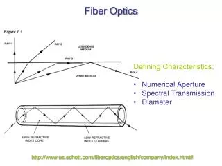
Principal of Guiding Light Refracted Ray Reflected Ray Incident Ray Normal • Light from Rarer to Denser medium: Speed slows down, Light bend towards the normal • Light from Denser to Rarer medium: Speed increases, Light bend away from the normal
Principal of Guiding Light Angle of Incidence on Core-Cladding Interface is Small • Large amount of light leaks in to the cladding. • Light in cladding is lost. Minimize the light leaking into the cladding
Principal of Guiding Light Angle of Incidence on Core-Cladding Interface is Increased but still Small • Amount of light leaking into cladding is reduced
Principal of Guiding Light Angle of Incidence on Core-Cladding Interface is equal to Critical Angle (Total Internal Reflection) Corning SMF-28: • Light incident at Critical angle travels along the core-cladding interface. • None of the Incident Light leaks into cladding. • The phenomenon is known as Total Internal Reflection.
Principal of Guiding Light Angle of Incidence on Core-Cladding Interface > Critical Angle Corning SMF-28: • All of the Incident light is reflected back into the core • Complete light is guided along the core
Principal of Guiding Light Cone of Acceptance or Light Cone Cone Of Acceptance Incident Light • If angle of incidence light is within the angle limited by the Cone of Acceptance, the light will be guided into and carried by the core, without leaking into the cladding.
Principal of Guiding Light Numerical Aperture Numerial Aperture Incident Light • The larger the value of Numerical Aperture, the more is the amount of light accepted • But leads to multipath and dispersion, causing signal broadening and loss. • High speed systems uses Fiber with very low value of Numerical Aperture
TOPICS • Introduction to Fiber Optics • Benefits of using Fiber Optics over traditional systems • Principal behind Fiber Optics • Technical Terms related to Fiber Optics Network • Practical Fiber Optics Network • Optical Network Components • Fiber optical Network in Aircrafts
Classification of Optical Fibers Multi-Mode Fiber Single-Mode (Mono-Mode) Fiber • Core Diameter: 8 – 10 μm • Low value of Acceptance Angle • Prone to damage • Light Source: LASER (Narrow Linewidth) (Costly) • Relatively costly to manufacture • Core Diameter: 50 – 200 μm • High value of Acceptance Angle • Mechanically more sturdy • Light Source: LED (Lambertian Beam, more Linewidth) (Cheap) • Cheaper to manufacture
Classification of Optical Fibers Disadvantages Multi-Mode Fiber Single-Mode (Mono-Mode) Fiber • Reduction in multipath, reduces Intermodal Dispersion and increases Data Rate • Intrinsic property of the fiber material introduces Chromatic Dispersion • Intermodal Dispersion: Multipath for light rays interact with each other, leading to broadening of pulse. • Results in high ISI and reduce Bitrate • Max. Bitrate: 100 Mbps
Classification of Multi-Mode Fibers Multi-Mode Fiber Graded Index Fiber Step Index Fiber • Silica core is doped with Germanium or Fluoride, reducing number of multipath and Intermodal Dispersion • Doping profile is parabolic • Max. Data-rate: 1 GBps-km • High material discontinuity at the core-cladding interface • Increases the number of light multi-path and increases intermodal dispersion • Max. Data-rate: 1 MBps-km
Optical Fiber Losses Intrinsic Losses Extrinsic Losses • Losses inherent to the Fiber • Cannot be avoided once the Fiber construction is complete • Is important factor for selecting fiber profile • Losses incurred due to layout of optical network • Can be controlled by selecting proper routing design and using good optical components
Optical Fiber Losses Intrinsic Losses Extrinsic Losses Absorption Loss Bending Loss Scattering Loss Launching Loss Connector Loss
Intrinsic Losses: Absorption Loss • Intrinsic Material Absorption: • Interaction of Light with Core material’s atomic constituent • Select a material which exhibit minimum absorption in the band of interest • The band of interest must lie outside the Material’s Atomic Resonance frequency to avoid absorption • Silica glass exhibit IR absorption band outside the optical communication band 0.8 – 0.9 μm and 1.2 – 1.5 μm. • Extrinsic Impurity Ion Absorption: • Caused by metal ion impurities (Fe2+,Cu2+, Cr3+ions), OH- ion trapped in Silica glass. • Impurities adjusts the material’s absorption spectrum by shifting or introducing new resonant frequency • The OH- absorption for ultrapure optical fiber offers fiber attenuation of at least 0.2 dB/km.
Intrinsic Losses: Scattering Loss • Scattering cause light travelling through the core to undergo elastic collision with scattering core (silica atoms, impurity ions), and spread out in all possible directions • These results in loss of light travelling through the core • Scattering loss is about 0.15 dB/km at 1550 nm wavelength
Extrinsic Losses: Bending Loss Macro-Bending Loss • Fiber is mechanically bent so much so that light leaks out of the core • Macro-bend loss increases as bent (radius of curvature) is increased • Corning-SMF 28e SMF (Single Mode Fiber) should not be bent below radius of 3 inches
Extrinsic Losses: Bending Loss Micro-Bending Loss • Small scale bend between core-cladding interface • These are localized bend which can develop due to stress developed during layout, wrapping of fiber in a fiber spool • These can occur due to unclean interface during manufacturing • Micro-bend loss adds 1-2 dB/km attenuation
Extrinsic Losses: Launching Loss • When connecting two fiber endings, they must be properly aligned (core axis of both fiber must be aligned) • Misalignment causes reflection and cause lesser amount of light to be accepted by the fiber
Extrinsic Losses: Connector Loss • Connectors hold fiber in place • Due to air interface between connector and fiber, reflection takes place • Total light introduced to the fiber is reduced • Modern Connector offers very low losses (~ 0.2 dB) • Rule of Thumb: Estimated Connector loss = 1 dB per connector
Attenuation in Optical Fiber • Attenuation causes light intensity to decrease as it travels through the optical fiber • Attenuation is caused by Intrinsic losses and excludes extrinsic losses (technically) • Attenuation is characterized by Attenuation Coefficient • Attenuation Coefficient: The optical power lost per unit distance, due to fiber (intrinsic losses) itself • At 1550 nm (Optical Communication Wavelength), the fiber attenuation is minimum (Attenuation Coefficient ~ 0.2 dB/km)
TOPICS • Introduction to Fiber Optics • Benefits of using Fiber Optics over traditional systems • Principal behind Fiber Optics • Technical Terms related to Fiber Optics Network • Practical Fiber Optics Network • Optical Network Components • Fiber optical Network in Aircrafts
Practical Optical Networks • Boeing 777 is the first commercial aircraft employing optical fiber LAN based on-board data communication network • System was developed during 1980s • The system employs: • AVionics Local Area Network (AVLAN) • Placed in Flight Deck and Electrical Equipment bay • CABin Local Area Network (CABLAN) • Fitted on the top of roof of the passenger cabin • The Network conforms to ARINC 636 standards • Maximum possible data rate is 100 Mbps • Multimode fiber is used for network layout • Multimode fiber are more sturdy (mechanically), cheap to manufacture and easy to layout
Practical Optical Networks Boeing 777
Fiber Optic Data Bus Optical Receiver Light – Electrical Conv. Data Sink Elec. Signal (OUT) Data Source Electrical Signal (IN) Optical Modulator (Light Source) Electrical – Light Conv. Multimode Fiber Carry Light through the Core • Photodiode • LED • Cheap • Broad spectrum (Line width) • Not monochromatic • Low speed (for modulation) • Laser • Costly • Narrow spectrum (Line Width) • Monochromatic • High Speed (for modulation)
Fiber Optic Cable Construction • Components: • 5 optical fiber • Buffer Coated with Distinct Colours for Identification • Colours: Blue, Red, Green, Yellow, White • 2 filler strands (mechanical support) • Separator tape • Aramid Yarn Strength Member • Outer Jacket Common SMF/MMF-Cable Specs:
Fiber Optic Connectors • Characteristics: • Reliable • Robust • Precise and can be used many number of times • Suitable for installation without using special tools • Low Loss (approx. 0.5 dB/connector; technically approximated as 1 dB/connector) • Low Cost
Fiber Optic Connectors • Connectors have following sections: • Alignment Keys and Grooves • Accurately align connectors of optical components • Minimizes connector loss • Guide Pins and Cavities • Guards fiber from damages due to over-tightening • Pins acts as buffer stop, at the bottom of the cavity receptable • Coloured Alignment beads • Coupling nut on plug barrel has Yellow band • Receptable side has Red and Yellow band • Correct connection: Red band of Receptable is at least 50 % covered • 3 Threads on both plug and receptable ensure a straight start when they join
SMA Connectors • SMA stands for Sub-Miniature version A • SMA is popular fiber optics connector used due to its ruggedness • SMA connector have a metal body, with precision hole in the tip • A striped fiber is firmly inserted into the SMA assembly after proper alignment, and secured with epoxy • Strength member is rigidly affixed with the body assembly to improve rigidity • Excess fiber is removed, the polished to desired length to provide optical finish • The connector mates with screw-type coupling mechanism until secure and aligned.
TOPICS • Introduction to Fiber Optics • Benefits of using Fiber Optics over traditional systems • Principal behind Fiber Optics • Technical Terms related to Fiber Optics Network • Practical Fiber Optics Network • Optical Network Components • Fiber optical Network in Aircrafts
Other Network Components • Couplers (3 or 4 ports) • Switches for redirecting the light beams into different strands • Routers for routing signals through the LAN. Comprises of • Switches • Processors • Controllers • Bus Interfaces
Bypass Switch Unit (BSU) • Optical Router sends control signals to Bypass Switch Unit (BSU) • BSU Control Signals: • PRI HI : Active HIGH connect BSU to fiber optic ring network • PRI RTN : Active LOW input connect Control signal to Optical Ground • SEC HI : Active HIGH connect BSU to fiber optic ring network • SEC RTN : Active LOW input connect Control signal to Optical Ground • Fiber Optic Interface: • Converts Electrical to Optical signal, and Optical to Electrical Signal • Interfaces BSU with electrical sections of the network
(Passive) Coupler Types • Divide input light equally among the output port • Types: • Star Couplers • Directional Couplers • Tee Couplers
Optical (Directional) Couplers • Multiple I/O ports for the light to travel • Lights in multiple port interact through light modes which leaks when the core are brought near each other • Light enters through port-1 and exit through Port-3, 4. No light should exit through Port-2. • Losses: Scattering, Absorption, Reflections and Cable Misalignment
Tee and Star Couplers • Tee Couplers • Star Couplers • Shaped as a Star: M-inputs, N-outputs • Delivers optical power to multiple terminals, suitable for connecting large number of terminals • Optical (Insertion) Power loss not directly proportional to the number of terminal ports • Shaped as a T : 1 input, 2 outputs • Divides input light power equally among the 2 output terminals • Optical Power Loss proportional to the number of output (terminal) nodes
TOPICS • Introduction to Fiber Optics • Benefits of using Fiber Optics over traditional systems • Principal behind Fiber Optics • Technical Terms related to Fiber Optics Network • Practical Fiber Optics Network • Optical Network Components • Fiber optical Network in Aircrafts
Application in Aircraft • Due to High-Bandwidth availability, Fiber optics was used in In-Flight Entertainment (IFE) systems Panasonic IFE on Boeing 737-800 (https://www.panasonic.aero/inflight-systems/x-series/systems/)