Download
1 / 47
470 likes | 488 Views
FP 420 BPM Workshop Signal Processing for BPMs Marek GASIOR CERN-AB-BI. Comparison among signals processing for BPM G. Vismara. Introduction Signal analysis Design parameters System families System descriptions. Introduction. Very large evolution since early days

E N D
FP 420 BPM Workshop Signal Processing for BPMs Marek GASIOR CERN-AB-BI FP 420 BPM Workshop
Comparison among signals processing for BPM G. Vismara Introduction Signal analysis Design parameters System families System descriptions BIW-00 May 8 - 11
Introduction • Very large evolution since early days • Processing choice depends on machine parameters • No unique solution • Wide range of signal processing: • Individual • Multiplexed (MPX) • Difference-over-Sum (D / S) • Normalization (Phase & Time) BIW-00 May 8 - 11
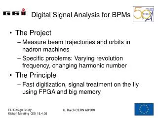
Signal analysis • Beam current Ib = [Qb*Nb]/trev Qb = charge/bunch, Nb = number of bunches, trev = revolution period • Ib or Qb ? • Ib measurements over several revolution cycles • Qb measurements on individual bunches • Induced signal V (t) = Zt*Ib (t) Zt is the PU’s transfer impedance • Bunch shape: (longitudinal charge density) • Gaussian for leptons, (Cosine)2 for protons • Bunching factor: • BF = (Bunching period)/(Bunch widthfwhm) BIW-00 May 8 - 11
Beam structure (rf bucket filling) • Un-bunched beam • Un-structure beam. No rf (Protons & Heavy Ions machines). Very difficult to be treated. • All • Beam bunches in all rf bucket. Optimized for maximum Ib (SPS) The easiest to be treated. Almost monochromatic freq.spectrum • Few • Beam bunches in few rf bucket with longitudinal symmetry. The highest bunch density (LEP). • Variable • Particular structure (no longitudinal symmetry); it includes single bunch filling and single passage (transfer lines) BIW-00 May 8 - 11
Beam structures BIW-00 May 8 - 11
Signal processing methods • The beam position is uniquely related to the amplitude ratio of the induced signals on opposite electrodes. • Processing methods for position calculation: • Difference over Sum (D/S) • Analog and Digital process • Amplitude to phase/ time • Passive analog process • Log-ratio (logA-logB) • Active analog process BIW-00 May 8 - 11
C B 1U A -1U 0 r = Kx,y D Reference parameter Position = Kx,y* (A-B)/(A+B) = Kx,y*Np Kx,y = scaling factor; A, B = induced signals; Np = Normalized Position Np is dimensionless and varies between 1U passing through 0 for a centered beam. 1U is the “Normalized half aperture” Na • The “Normalized half aperture” should be the reference parameter when specifying a processing system. • This will make possible comparisons among systems BIW-00 May 8 - 11
Parameters: Accuracy • The ability to minimize the beam position errors • Error sources: • mechanic, magnetic and electronics causes • The offset for a centered beam should be minimized • Beam based alignment techniques • Electronics error sources: • Impedance mismatching on interconnecting cables • Electromagnetic interference and noise on the input stage • Non-linearity and beam intensity dependence • Channels gain differences and calibration errors • Digitizer granularity BIW-00 May 8 - 11
Parameters: Resolution • Important in colliding machines for luminosity • Minimum position difference that can be resolved • Single shot: • Stdev of individual measurements referred to the normalized aperture • Averaged: • as above but integrated over several revolutions • Limiting factors: • At low level, it depends on the input noise and the BW • For large signals, on the ADC resolution and the time jitter • State of art resolutions : • Single shot: < 0.02% of Na (few micron) • Averaged : < 20 ppm of Na (sub-micron) BIW-00 May 8 - 11
Parameters: Stability • The measurement’s uncertainty will affect the global resolution of system. • The position measurements should be independent of the beam intensity, the bunch shaping and the rate. • They should be stable vs. temperature and time, at least during the time interval between two calibrations • Stability versus input signal • Stdev from a series of digitized positions measured over the whole dynamic range. • Position temperature coefficient • Slope of the position drift versus temperature • Long term position stability • Stdev of a series of digitized positions versus time BIW-00 May 8 - 11
Parameters: Sensitivity & Dynamic • Sensitivity: • The minimum input level at which a beam position measurement still fulfills the accuracy specifications (> 107 p/b) • Dynamic • It determines the capability of the system to absorb very different beam intensities conditions • It’s defined as the difference, expressed in dB, between the maximum input level before a large non-linearity on the output signal appears (saturation) and the minimum input level at which a pre-defined signal to noise ratio (S/N) is reached • Processors using a discrimination level will not be limited by the S/N ratio, the lower limit being determined by the discriminator's threshold. BIW-00 May 8 - 11
Parameters: Acquisition time • The time required for the signal processor to store a full set of data into the memory • The importance of this parameter is related to the capability of resolving individual bunches and the absolute resolution of the processor • Several elements contribute to build-up this time: • The LP and BP filters • The switching and acquisition time (MPX processors) • The PLL’s time to synchronize (synchronous detector) • The AGC’s set-up time (constant sum) • The S&H circuit and the ADC’s conversion time BIW-00 May 8 - 11
AdvantagesWeakness Large BandwidthLimited dynamic Long term stabilityNo turn by turn Center stabilityGain switching Amplitude No intensity independent information Signals recombination Individual Multiplexed Electrodes A, B D / S Passive Normalization Processing system families BIW-00 May 8 - 11
No intensity information Reduced N°of digitizing bit Advantages Weakness Long term stabilityGain matching Large dynamic Limited linearity Large Bandwidth Time matching SimplicityPhase matching Normalization Process Constant Sum Logarithmic conversion Normalizers Amplitude to time Amplitude to phase Processing system families Active process Passive process BIW-00 May 8 - 11
Definition Types Individual bunches - Track & Holdseparated by >10 ns- Log amplifiersto single - Amp to Time Normalizer Turn-by-turn- Heterodyne or individual bunches - Amplitude to separated by >100 ns Phase normalizer Non consecutive -MPX turns measurements Wide Band Narrow Band Acquisition Time Slow Acquisition Processing system families Time Domain BIW-00 May 8 - 11 Frequency Domain
AGC on S D I G I T I Z E R Synchronous Detection Heterodyne MPX POS = (A-B) no turn by turn Hybrid D / S Homodyne Detection Heterodyne POS = D / S Sample,Track, Integr. & Hold Switch. gain Amplifier Electrodes A, B POS = D / S or = (A-B)/(A+B) Differential Amplifier Individual Treatment Logarithm. Amplifiers POS = [log(A/B)] = [log(A)-log(B)] Legend: / Single channel Wide Band Narrow band Passive Normaliz. Limiter, Dt to Ampl. POS = [A/B] Amp. to Phase . Limiter, f to Ampl. POS = [ATN(A/B)] Normalizer Processor Active Circuitry Processing system families turn by turn Amp. to Time BIW-00 May 8 - 11
Limiter Freq. Synt. VCO PLL VLSI BP Filter Pre- Ampl IF. Ampl A Mixer A Mixer X B Active Matrix AGC B BP Filter BP Filter S Y MPX MPX C C D D MPX schematics BIW-00 May 8 - 11
MPX description • Conceived for closed orbit of stable stored beams • The input signals are sequentially multiplexed into a single receiver • Multi-stage configuration of GaAs switches (Channels isolation >50 dB) • A BP filter selects the largest line of the spectrum • Pre-amplifier with AGC. Large input dynamic (>80 dB) and gain control (>50 dB)Noise Figure difficult to optimize. • Active mixer, driven by a frequency synthesizer, down convert to standard IF • IF amplifier with AGC and synchronous detection, by comparing the phase of a sample of carrier signal with a reference signal via a VCO in a phase lock loop (VLSI) • BP filter to suppress side-bands (100 kHz > BW< 1MHz). • De-multiplexer, Track & Hold and active matrix produce 7 signals (A, B, C, D, Sum, X, Y) store theirs values in four analog memories BIW-00 May 8 - 11
Reduced number of channels (x4) Identical gain for all the channels No need for gain selection (AGC) Large dynamic range (>80dB) Excellent position stability No temperature dependence and components aging. Reduced N° of bits at equivalent resolution (Normalization) Stable beam during the scanning No turn by turn acquisition Slow acquisition rate (MPX) Reduced Noise Figure (front end matching & MPX insertion losses, AGC pre-ampli.) Reduced linearity, for non-linear PU’s since the S is not constant Large engineering No intensity information (AGC) MPX performances Limitations Advantages BIW-00 May 8 - 11
LP Filter Pre- Ampl Sample & Hold Mixer Wide band processing 0° 0° Pre Ampl Sample & Hold Limiter A 0° 180° 0° 0° LP Filter Pre- Ampl Sample & Hold 180° 0° B Pre Ampl Sample & Hold Mixer BP Filter Narrow band processing D A D BP Filter B S S Difference over Sum (D/S) BIW-00 May 8 - 11
The D and S signals are obtained from a passive four port 180° hybrid Wide-band It offers wide-band response (from kHz to GHz over >3 decades), very large dynamic only limited by the electronics, isolation among ports (>30 dB) Programmable gain amplifiers (Ga As switches) and track or peak & hold circuits Wide bunches may be directly digitized by FADC (>1 GS/s) A & B signals can be treated separately by suppressing the 180° hybrid Narrow-band BP filters are used to select the largest line in the spectrum. Programmable gain amplifiers and homodyne detector (a fraction of S signal is limited and used as local oscillator). Track & Hold and an externally triggered ADCs, digitize the D and S signals Difference over Sum (D/S) description BIW-00 May 8 - 11
[W.B.] & {N.B.} The central position independent on input intensity. Intensity measurement available Excellent Noise Figure [Wide band allows measurements on multiple bunches (Dt <20 ns)] { Large dynamic > 90 dB} Programmable gain amplifiers Multiple calibration coefficients The absolute position is f(gain) {Tight phase matching(D, S) at all the gainsrequired by the synchronous detection (5°) } { Pedestal error on S } Difference over Sum ( D / S ) performances Limitations Advantages BIW-00 May 8 - 11
LP Filter LP Filter Logarithmic amplifier schematics • Each signal is compressed by a logarithmic amplifier, filtered and applied to a differential amplifier. • The position response isPos. [log(A/B)] = [log(A)-log(B)] (Vout)where Vout is the voltage difference between the log-amplifiers outputs I to V Converter Logamp A Diff. Ampli B Position = K * Vout I to V Converter Logamp BIW-00 May 8 - 11
Logarithmic amplifier description • New generation circuits use several cascaded limiting amplifiers, with fix gain and wide bandwidth. Full wave rms detectors are applied among each stage and by summing theirs output signals, a good approximation to a logarithmic transfer function is obtained. Typical parameters are: • Input dynamic range : >90 dB • Input noise: < 1.5 nV/Hz • Non conformance lin.: < 0.3 dB • Limiter Bandwidth: D.C. to >2 GHz • Video Bandwidth: D.C. to 30 MHz BIW-00 May 8 - 11
Possible applications in the time and frequency domain (NB & WB) Very large dynamic range (>90 dB) without gain adjustment Wide input bandwidth No bunch shape dependency Simultaneous digitization of individual + and - charges Auto-triggering capability Simple engineering State of art performances are not simultaneously available Poor position stability vs.. input level, for particular conditions Limited linearity ( few % of the normalized aperture) Limited long term stability Temperature dependence Logarithmic amplifiers performances Limitations Advantages BIW-00 May 8 - 11
The Front-End Electronics BI Review - Rhodri Jones (CERN - SL/BI)
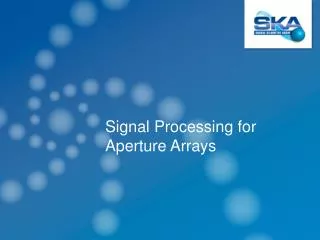
A + (B + 1.5ns) A B Beam 1.5ns B + 1.5ns The Wide Band Time Normaliser A B BI Review - Rhodri Jones (CERN - SL/BI)
A B A + 1.5ns 1.5ns B + (A + 1.5ns) Dt depends on position The Wide Band Time Normaliser A + (B + 1.5ns) A B BI Review - Rhodri Jones (CERN - SL/BI)
The Wide Band Time Normaliser A B A+(B+1.5ns) B+(A+1.5ns)+10ns Interval = 10 1.5ns System output BI Review - Rhodri Jones (CERN - SL/BI)
The Wide Band Time Normaliser BI Review - Rhodri Jones (CERN - SL/BI)
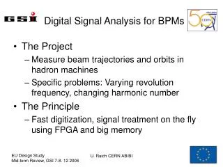
WBTN - Linearity v Intensity For LHC Arc BPMs 1% ~ 130mm BI Review - Rhodri Jones (CERN - SL/BI)
WBTN - Linearity v Position For LHC Arc BPMs 1% ~ 130mm BI Review - Rhodri Jones (CERN - SL/BI)
3 = 750m 20% of 4mm Closed Orbit ‘budget’ (Spec = 500m) Accuracy and Resolution BI Review - Rhodri Jones (CERN - SL/BI)
Reduced number of channels (x2) No need for gain selection Input dynamic > 50 dB Signal dynamic independent on the number of bunches ~10 dB compression of the position dynamic (recombination) Acquisition rate > 40 MS/s Auto-trigger Reduced N° of bits at equivalent resolution (Normalization) Mainly reserved to bunched beams Tight time adjustment Propagation delay stability and switching time uncertainty are the limiting performance factors No Intensity information Remark: A specifically designed monolithic Ga-As chip will allow for a large speed breakthrough Amplitude to Time Normalizer performances Limitations Advantages BIW-00 May 8 - 11
Analog Digital a Analog demodulator and filter 1st analog frequency translator 2nd analog frequency translator output ADC Pick-up or sensor Supplying rf signal Evolution of radio systems: as processing and sampling technologies improve, digital moves from the baseband end (a) towards the pick-up sensor (b). b Analog frequency translator Digital frequency translator Digital demodulator and filter Digital signal processor (DSP) output ADC Digital receiver (basic) • Digital receiver is a new approach of the heterodyne receiver • The basic functionality is preserved but implemented differently • Present situation allows to place the digital transition just after the IF amplifier BIW-00 May 8 - 11
Programmability Narrow and wide band processing Identical gain for all the channels due to possible permanent calibration Resolution may be improved by over-sampling techniques Excellent linearity (ADC) Large dynamic range (AGC) Reduced N° of bits at equivalent resolution (Normalization) No single shot measurement No “plug and play” system Large engineering All problems related to a new un-experienced processing system The present advantages alone do not justify the man power investment, but I consider this technique as one of the most promising for the future Digital Receiver performances Advantages Limitations BIW-00 May 8 - 11
Conclusions for FP 420 BPMs • No obvious solution to satisfy all FP 420 BPM requirements, especially • Required „normalized accuracy” in the order of 10 um / 100 mm, i.e. 10-4 • Bunch by bunch measurement • Already „bunch by bunch” resolution in the order of 10-4 is difficult to achieve • Propositions • Measurement with a single multiplexed channel for a few bunches • Something special, which employs specific features of the FP 420 BPM system • What can help to relax the difficult requirements? • Required accuracy concerns relative distance beam – SI detector • Required measurement range is much smaller than the vacuum chamber diameter FP 420 BPM Workshop
An idea of a PU with reduced „working aperture” • A „collimator arrangement” to reduce the PU „working aperture” • If the jaw distance can be reduced to some 10 mm, then the „normalized accuracy” drops to 10-3, which is much more reasonable • One PU electrode on one unit with the Si detector, giving excellent relative positioning • Jaw relative position measured with optical means • Possible dynamic jaw positioning with respect to the beam • Some know-how could be quickly transferred from the collimator people, especially if they could think about using a similar idea for the collimator system FP 420 BPM Workshop
A version more robust for scattered particles • This version may be also interesting for collimators, for symmetric jaw positioning with respect to the beam • Signal quality not very demanding for simple signal equalization from both probes FP 420 BPM Workshop
Spare slides FP 420 BPM Workshop
Wall Current Monitor (WCM) principle • The BEAM current is accompanied by its IMAGE • A voltage proportional to the beam current develops on the RESISTORS in the beam pipe gap • The gap must be closed by a box to avoid floating sections of the beam pipe • The box is filled with the FERRITE to force the image current to go over the resistors • The ferrite works up to a given frequency and lower frequency components flow over the box wall FP 420 BPM Workshop
WCM as a Beam Position Monitor • For a centered BEAM the IMAGE current is evenly distributed on the circumference • The image current distribution on the circumference changes with the beam position • Intensity signal () = resistor voltages summed • Position dependent signal () = voltages from opposite resistors subtracted • The signal is also proportional to the intensity, so the position is calculated according to / • Low cut-offs depend on the gap resistance and box wall (for ) and the pipe wall (for ) inductances FP 420 BPM Workshop
An eight electrode “tight” design to avoid resonances in the GHz range The electrodes cover 75 % of the circumference The electrode internal diameter is only 9 mm larger then the vacuum chamber of 40 mm and it is occupied by the ceramic insertion (alumina) The transformers are as small as possible to gain high frequency cut-off with many turns The transformers are mounted on a PCB The connection between the electrodes and the cover is made by screws Electrode diameter step is occupied by the ceramic tube The tube is titanium coated on the inside A new design: Inductive Pick-Up (IPU) MORE INDUCTANCE LESS RESISTANCE FP 420 BPM Workshop
The CMRR at 100 MHz is as high as 55 dB (datasheet 42 dB) The CMRR for frequencies below 10 MHz is limited by the measurement setup signal high cut-off frequency about 200 MHz Active Hybrid Circuit – Performance FP 420 BPM Workshop
IPU and AHC – Frequency Characteristics • A wire method with a 50 coaxial setup which the IPU is a part • signal – flat to 0.5 dB within 5 decades, almost 6 decades of 3 dB bandwidth (no compensation) • signal – 5 decades (four decades + one with an extra gain for low frequencies) BW: 300 Hz – 250 MHz ( 6 decades) BW: 1 kHz – 150 MHz (> 5 decades) FP 420 BPM Workshop
IPU and AHC – Displacement Characteristics A thin wire forming a coaxial line was displaced diagonally across the pick-up aperture. The measurement was done with a network analyzer: signal was applied to the wire and hybrid signals were observed. FP 420 BPM Workshop