Download
1 / 13
250 likes | 1.12k Views
Smart Dust Mote Core Architecture. Brett Warneke, Sunil Bhave CS252 Spring 2000. Smart Dust Overview. Autonomous sensing and communications in 1 mm 3 Multiple sensors: temperature, light, vibration, etc. Batteries: 1 J/mm 3 Downlink:broadcast only Uplink: CCR draws 6.4pJ/bit.

E N D
Smart Dust Mote Core Architecture Brett Warneke, Sunil Bhave CS252 Spring 2000
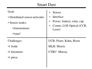
Smart Dust Overview • Autonomous sensing and communications in 1 mm3 • Multiple sensors: temperature, light, vibration, etc. • Batteries: 1 J/mm3 • Downlink:broadcast only • Uplink: CCR draws 6.4pJ/bit
System Diagram • Core • Transceiver back end • Sensor Signal Processing • Computation • Memory Sensors Power Supply ADC Receiver Front End CCR Driver Real Time Clock
Design Goals • Minimize energy through architecture • Minimum energy Þ ASIC implementation • Dynamic reconfigurability • How much is necessary ® tradeoff with ASIC mapping • Energy driven operation modes • Military base monitoring • Typical application scenario to guide design • Detect heat and vibration of vehicles • Real time sensor readings • Logged sensor readings ASIC Microprocessor
Desired Operations • Immediate • Transmit ID Mote health report • Transmit current readings from one/all sensors • Send logged data for sensor X • Calibrate real-time clock • Reconfiguration • Start logging data from sensor X sampled every T seconds • Set logging threshold and filter coefficients • Set ‘ScatterCast’ interval to T seconds • Set your wakeup interval to T seconds
Golden Processor: Features • Laser Reprogrammable • Gated clocks everywhere • Processor stall mode • Eight execution phases • 1 cpi including fetch • No pipelining to reduce overhead • Forced sequencing • Minimize glitching • Prevent bus conflicts and thus short circuit current • Robust to delay variations from process spreads, voltage swings (will test from 0.3V to 1.4V), and temperature
New Approach: Top-Level Diagram Sensors Setup Memroy Timer Bank Power Supply ADC Receiver Front End Reconfigurable Datapath Components CCR Driver Real Time Clock SRAM
Timers and Setup Memory Timer value 1 Timer value 2 Timer Setup Mem 1 Setup Mem 2 • All activity initiated by timers • When timer expires, Setup Memory 1 configures the datapath • Additional setup memories can be invoked to perform more steps • Two rates available for each timer • Two sensor sampling rates for normal polling and interesting events • Delay receiver for a long period before returning to normal rate • Multiple setup memory banks for energy-driven operationmodes
Reconfigurable Datapath Components Adder Config Mem Config Mem Timing Recovery Data Recovery Sensor Reg n Data Addr Reg Mote ID Mem Comparator Packet Decoder Packet Encoder FFT FIR Filter CRC FIFO Immediate Mode Setup Reg Global Setup Reg • Immediate mode packets load Immediate Mode Setup Register to configure the datapath • Data-driven components • Wiring options • many point-to-point control and data wires • wire mesh with switches for routing Threshold Mem n
Example Configuration: Sensor Logging Setup Mem 1 Setup Mem 1 True Setup Mem 2 Setup Mem 2 Zero Open control signals are driven by the setup memory Open control signals are driven by the setup memory Open control signals are driven by the setup memory Done Done Done PWR PWR PWR PWR PWR PWR PWR ADC Sensor PWR Done ADC Sensor Data Data Data PWR PWR Done Done Adder Adder Done Done False False Data WE WE Data Data SRAM SRAM Comparator Comparator True True PWR Data Data PWR PWR PWR PWR Addr Addr Sensor Reg Threshold Mem Threshold Mem Sensor Reg PWR PWR Data Addr Reg Data Addr Reg Timer value 1 Timer value 2 Setup Mem 1 Timer 4 3 2 1 0 5 Setup Mem 2 Zero Open control signals are driven by the setup memory Done PWR PWR PWR ADC Sensor PWR Done Data Adder Done False Data WE SRAM Comparator True PWR Data PWR Addr Sensor Reg Threshold Mem PWR Data Addr Reg
Comparison of Three Architectures • ARM8 estimations from Peggy Laramie, M.S. thesis 1998 • energy is for a set of instructions equivalent to the configuration on the previous slide • Vdd=1V (scaled from the reported numbers) • Energy estimations for other approaches were to be from Powermill
Conclusions • Smart Dust needs minimum energy controller • New non-microprocessor architecture designed • Timer controlled • Reconfigurable datapath • Should be much lower energy than a microprocessor architecture, but unconfirmed