Download

1 / 16
160 likes | 300 Views
Realizing 3D Smart Dust Particles. Zeynep Dilli. Introduction & Outline. MIT Lincoln Laboratories FDSOI Process: Adapted to chip stacking 3D Run in April 2005 Outline: System Description Process information Photodiodes: Design and Layout Simulation Results Layouts. Proposed System.

E N D
Realizing 3D Smart Dust Particles Zeynep Dilli
Introduction & Outline • MIT Lincoln Laboratories FDSOI Process: Adapted to chip stacking • 3D Run in April 2005 • Outline: • System Description • Process information • Photodiodes: Design and Layout • Simulation Results • Layouts
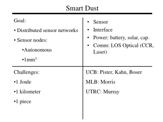
Proposed System • 3D system concept: Three tiers • Sensor (Energy harvesting/Photosensor) • Storage (Energy) • Electronics (Local Oscillator and Output Driver)
Proposed System • Submitted proposal for a self-powered local oscillator circuit • Area Assigned: 250 microns by 250 microns • Total size: 250 x 250 x 800 microns ip
Process information • 0.2 μm, fully depleted Silicon-on-insulator • Silicon islands 50 nm thick • Three-metal process • Three tiers stacked • Through-vias • Top two tiers turned upside-down Figure adapted from MIT_LL 3D01 Run Application Notes
Photodiodes: Design Issues • Photocurrent=Responsivity [A/W] x Incident Power • Responsivity= Quantum efficiency x λ[μm] /1.24 • For red light, λ[μm] /1.24 = 0.51 • Incident Power = Intensity [W/μm2] x Area [μm2] • Sunlight intensity ≈ 1x10⁻⁹ W/μm2 • Quantum Efficiency = [# electron-hole pairs]/ [# incident photons] • Depends on reflectance, how many carrier pairs make it to the outer circuit, and absorption • At 633 nm (red light), absorption coef. ≈3.5e-4 1/nm amount of photons absorbed in 50 nm depth is (1-exp(-αd))≈ 0.017 • η = 0.017 x reflectance x ratio of non-recombined pairs ≈ 0.017 x 0.75=0.013 • Photocurrent=0.013 x0.51 x 1x10-9 x Area[μm2] = 6.63 pA/μm2 • Major problem: The material depth is very small
Photodiodes: Design Issues • Photocurrent=0.013 x0.51 x 1x10-9 x Area[μm2] = 6.63 pA/μm2 • Photosensitive area is pn-junction depletion region width (Wd) times length • Available implants: Body threshold adjustment implants (p-type CBN and n-type CBP, both 5x1017 cm-3); higher-doped source-drain implants and capacitor implants; undoped material is p-type, ~1014 cm-3. • Two diode designs: CBN/CBP diode and pin diode (CBP/intrinsic junction) • CBN/CBP diode Wd=0.0684 μm; A=0.5472 μm2 • Pin-diode Wd ≈ 1.5 μm; A=15 μm2; possibly problematic • Layout: 2062 CBN/CBP diodes: 7.48 nA; 52 pin diodes: 5.17 nA • To increase: Higher-intensity light; optimal wavelength (higher wavelength increases λ/1.24, but decreases absorption) • Expect about 10 nA
Operation • ip=10 nA, C=30 pF
Operation • ip=10 nA, C=30 pF
Operation • ip=10 nA, C=30 pF
Operation • ip=40 nA, C=30 pF
Layout: Tier 2, Capacitor Top plate: Poly Bottom plate: N-type capacitor implant, CAPN Extracted value: 29 pF Expected value: 30 pF
Layout: Tier 3, Diodes and Pads “VDD” “GND” Oscillator output