Download
1 / 71
1.42k likes | 2.3k Views
Chapters – 5 & 6 Chapter -5 RESPONSE SPECTRUM METHOD OF ANALYSIS. 1/1. Introduction. Response spectrum method is favoured by earthquake engineering community because of: It provides a technique for performing an equivalent static lateral load analysis.

E N D
Chapters – 5 & 6 Chapter -5 RESPONSE SPECTRUM METHOD OF ANALYSIS
1/1 Introduction • Response spectrum method is favoured by • earthquake engineering community because of: • It provides a technique for performing an • equivalent static lateral load analysis. • It allows a clear understanding of the • contributions of different modes of vibration. • It offers a simplified method for finding the • design forces for structural members for • earthquake. • It is also useful for approximate evaluation • of seismic reliability of structures.
1/2 Contd… • The concept of equivalent lateral forces for earth- • quake is a unique concept because it converts a • dynamic analysis partly to dynamic & partly to • static analysis for finding maximum stresses. • For seismic design, these maximum stresses are • of interest, not the time history of stress. • Equivalent lateral force for an earthquake is • defined as a set of lateral force which will • produce the same peak response as that • obtained by dynamic analysis of structures . • The equivalence is restricted to a single mode of • vibration.
1/3 Contd… • Theresponse spectrum method of analysis is • developed using the following steps. • A modal analysis of the structure is carried out • to obtain mode shapes, frequencies & modal • participation factors. • Using the acceleration response spectrum, an • equivalent static load is derived which will • provide the same maximum response as that • obtained in each mode of vibration. • Maximum modal responses are combined to • find total maximum response of the structure.
1/4 Contd… • The first step is the dynamic analysis while , the • second step is a static analysis. • The first two steps do not have approximations, • while the third step has some approximations. • As a result, response spectrum analysis is • called an approximate analysis; but applications • show that it provides mostly a good estimate of • peak responses. • Method is developed for single point, single • component excitation for classically damped • linear systems. However, with additional • approximations it has been extended for multi • point-multi component excitations & for non- • classically damped systems.
1/5 Development of the method • Equation of motion for MDOF system under • single point excitation • (5.1) • Using modal transformation, uncoupled sets of • equations take the form • is the mode shape; ωi is the natural frequency • is the more participation factor; is the • modal damping ratio.
1/6 Contd… • Response of the system in the ith mode is • (5.3) • Elastic force on the system in the ith mode • (5.4) • As the undamped mode shape satisfies • (5.5) • Eq 5.4 can be written as • (5.6) • The maximum elastic force developed in the ith • mode • (5.7)
1/7 Contd… • Referring to the development of displacement • response spectrum • (5.8) • Using , Eqn 5.7 may be written as • (5.9) • Eq 5.4 can be written as • (5.10) • is the equivalent static load for the ith mode • of vibration. • is the static load which produces structural • displacements same as the maximum modal • displacement.
1/8 Contd… • Since both response spectrum & mode shape • properties are required in obtaining , it is known • as modal response spectrum analysis. • It is evident from above that both the dynamic & • static analyses are involved in the method of • analysis as mentioned before. • As the contributions of responses from different • modes constitute the total response, the total • maximum response is obtained by combining modal • quantities. • This combination is done in an approximate manner • since actual dynamic analysis is now replaced by • partly dynamic & partly static analysis.
2/1 Contd… • Three different types of modal combination rules • are popular • ABSSUM • SRSS • CQC Modal combination rules • ABSSUM stands for absolute sum of maximum • values of responses; If is the response quantity • of interest (5.11) is the absolute maximum value of response in the ith mode.
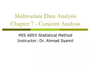
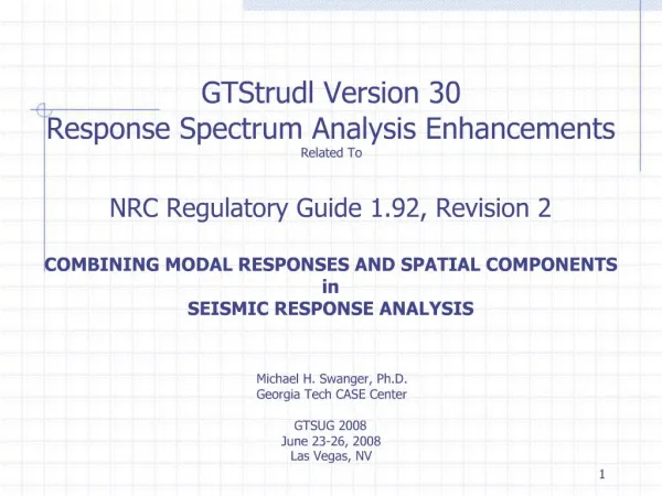
2/2 Contd… • The combination rule gives an upper bound to the computed values of the total response for two • reasons: • It assumes that modal peak responses occur at • the same time. • It ignores the algebraic sign of the response. • Actual time history analysis shows modal peaks • occur at different times as shown in Fig. 5.1;further • time history of the displacement has peak value at • some other time. • Thus, the combination provides a conservative • estimate of response.
0.4 0.2 Top floor displacement (m) 0 -0.2 -0.4 0 5 10 15 20 25 30 t=6.15 (a) Top storey displacement 0.4 0.2 0 First generalized displacement (m) -0.2 -0.4 t=6.1 0 5 10 15 20 25 30 Time (sec) 2/3 (b) First generalized displacement Fig 5.1
0.06 0.04 0.02 0 Second generalized displacement (m) -0.02 -0.04 -0.06 10 15 30 0 5 20 25 t=2.5 Time (sec) Contd… 2/3 (c) Second generalized displacement Fig 5.1 (contd.)
2/4 Contd… • SRSS combination rule denotes square root of sum • of squares of modal responses • For structures with well separated frequencies, it • provides a good estimate of total peak response. • When frequencies are not well separated, some • errors are introduced due to the degree of • correlation of modal responses which is ignored. • The CQC rule called complete quadratic • combination rule takes care of this correlation.
2/5 Contd… • It is used for structures having closely spaced • frequencies: • Second term is valid for & includes the effect • of degree of correlation. • Due to the second term, the peak response may be • estimated less than that of SRSS. • Various expressions for are available; here • only two are given :
2/6 Contd… • (Rosenblueth & Elordy) (5.14) • (Der Kiureghian)(5.15) • Both SRSS & CQC rules for combining peak modal • responses are best derived by assuming • earthquake as a stochastic process. • If the ground motion is assumed as a stationary • random process, then generalized coordinate in • each mode is also a random process & there • should exist a cross correlation between • generalized coordinates.
2/7 Contd… • Because of this, exists between two modal • peak responses. • Both CQC & SRSS rules provide good estimates of • peak response for wide band earthquakes with • duration much greater than the period of structure. • Because of the underlying principle of random • vibration in deriving the combination rules, the • peak response would be better termed as mean • peak response. • Fig 5.2 shows the variation of with frquency • ratio.rapidly decreases as frequency ratio • increases.
Contd… 2/8 Fig 5.2
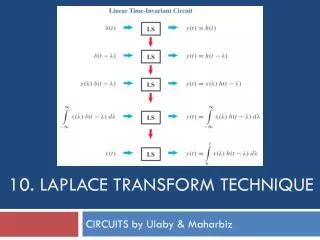
2/9 Contd… • As both response spectrum & PSDF represent frequency contents of ground motion, a relationship • exists between the two. • This relationship is investigated for the smoothed • curves of the two. • Here a relationship proposed by Kiureghian is • presented
0.05 Unsmoothed PSDF from Eqn 5.16a /rad) 3 Raw PSDF from fourier spectrum - 0.04 sec 2 0.03 0.02 0.01 PSDF of acceleration (m 0 0 10 20 30 40 50 60 Frequency (rad/sec) 0.025 Eqn.5.16a Fourier spectrum of El Centro /rad) 0.02 3 - sec 2 0.015 PSDFs of acceleration (m 0.01 0.005 0 0 10 20 30 40 50 60 70 80 90 100 Frequency (rad/sec) 2/10 Contd… Example 5.1 : Compare between PSDFs obtained from the smoothed displacement RSP and FFT of Elcentro record. Unsmoothed 5 Point smoothed Fig5.3
2/11 Application to 2D frames • Degree of freedom is sway degree of freedom. • Sway d.o.f are obtained using condensation • procedure; during the process, desired response • quantities of interest are determined and stored in • an array R for unit force applied at each sway • d.o.f. • Frequencies & mode shapes are determined • using M matrix & condensed K matrix. • For each mode find (Eq. 5.2) & obtain Pei • (Eq. 5.9)
2/12 Contd… • Obtain ; is the modal peak • response vector. • Use either CQC or SRSS rule to find mean peak • response. • Example 5.2 : Find mean peak values of top dis-placement, base shear and inter storey drift between 1st & 2nd floors. Solution :
2/13 Contd… Table 5.1
3/1 Application to 3D tall frames • Analysis is performed for ground motion applied to • each principal direction separately. • Following steps are adopted: • Assume the floors as rigid diaphragms & find • the centre of mass of each floor. • DYN d.o.f are 2 translations & a rotation; centers • of mass may not lie in one vertical (Fig 5.4). • Apply unit load to each dyn d.o.f. one at a • time & carry out static analysis to find • condensed K matrix & R matrix as for 2D frames. • Repeat the same steps as described for 2D • frame
3/2 Figure 5.4:
3/3 Contd… • Example 5.3 : Find mean peak values of top floor displacements , torque at the first floor & at the base of column A for exercise for problem 3.21. Use digitized values of the response spectrum of El centro earthquake ( Appendix 5A of the book). • Results are obtained following the steps of • section 5.3.4. • Results are shown in Table 5.2. Solution :
3/4 Contd… TABLE 5.2 • Results obtained by CQC are closer to those of • time history analysis.
3/5 RSA for multi support excitation • Response spectrum method is strictly valid for • single point excitation. • For extending the method for multi support • excitation, some additional assumptions are • required. • Moreover, the extension requires a derivation • through random vibration analysis. Therefore, it is • not described here; but some features are given • below for understanding the extension of the • method to multi support excitation. • It is assumed that future earthquake is • represented by an averaged smooth response • spectrum & a PSDF obtained from an ensemble • of time histories.
3/6 Contd… • Lack of correlation between ground motions at • two points is represented by a coherence function. • Peak factors in each mode of vibration and the • peak factor for the total response are assumed to • be the same. • A relationship like Eqn. 5.16 is established • between and PSDF. • Mean peak value of any response quantity r consists of two parts:
3/7 Contd… • Pseudo static response due to the displacements of the supports • Dynamic response of the structure with respect to supports. • Using normal mode theory, uncoupled dynamic equation of motion is written as:
3/8 Contd… • If the response of the SDOF oscillator to • then • Total response is given by • are vectors of size m x s (for s=3 & m=2)
3/9 Contd… • Assuming to be random processes, PSDF of is given by: • Performing integration over the frequency range • of interest & considering mean peak as peak • factor multiplied by standard deviation, • expected peak response may be written as:
3/10 Contd… • and are the correlation matrices • whose elements are given by:
3/11 Contd…
3/12 Contd… • For a single train of seismic wave, • that is displacement response spectrum for a specified ξ; correlation matrices can be obtained • if is additionally provided; can be determined from(Eqn 5.6). • If only relative peak displacement is required,third • term of Eqn.5.26is only retained. • Steps for developing the program in MATLAB is • given in the book. Example 5.4 Example 3.8 is solved for El centro earthquake spectrum with time lag of 5s.
3/13 Contd… • Solution :The quantities required for calculating the • expected value are given below:
3/14 Contd…
3/15 Contd… • Mean peak values determined are: • For perfectly correlated ground motion
3/16 Contd… • Mean peak values of relative displacement • It is seen that’s the results of RHA & RSA match • well. • Another example (example 3.10) is solved for a time • lag of a 2.5 sec. • Solution is obtained in the same way and results • are given in the book. The calculation steps • are self evident.
k Secondary System m c .. .. .. .. .. xa = xf + xg xg 4/1 Cascaded analysis • Cascaded analysis is popular for seismic analysis • of secondary systems (Fig 5.5). • RSA cannot be directly used for the total system • because of degrees of freedom become • prohibitively large ; entire system becomes • nonclasically damped. xf Fig 5.5 Secondary system mountedon a floor of a building frame SDOF is to be analyzed forobtaining floor response spectrum
4/2 Contd… • In the cascaded analysis two systems- primary • and secondary are analyzed separately; output of • the primary becomes the input for the secondary. • In this context, floor response spectrum of the • primary system is a popular concept for • cascaded analysis. • The absolute acceleration of the floor in the figure • is • Pseudo acceleration spectrum of an SDOF is • obtained for ; this spectrum is used for RSA of • secondary systems mounted on the floor.
1.5 Displacement (m) 1 0.5 0 0 5 10 15 20 25 30 35 40 Frequency (rad/sec) 4/3 Contd… • Example 5.6For example 3.18, find the mean peak displacement of the oscillator for El Centro earthquake. • for secondary system = 0.02 ; for the main • system = 0.05 ;floor displacement spectrum shown in the Fig5.6 is used • Solution • Using this spectrum, peak displacement of the secondary system with T=0.811s is 0.8635m. • The time history analysis for the entire system (with C matrix for P-S system) is found as 0.9163m. Floor displacement response spectrum (Exmp. 5.6)
Approximate modal RSA 4/4 • For nonclassically damped system, RSA cannot • be directly used. • However, an approximate RSA can be performed. • C matrix for the entire system can be obtained • (using Rayleigh damping for individual systems • & then combining them without coupling terms) • matrix is obtained considering all d.o.f. & • becomes non diagonal. • Ignoring off diagonal terms, an approximate • modal damping is derived & is used for RSA.
Seismic coefficient method 4/5 • Seismic coefficient method uses also a set of • equivalent lateral loads for seismic analysis of • structures & is recommended in all seismic codes • along with RSA & RHA. • For obtaining the equivalent lateral loads, it uses • some empirical formulae. The method consists of • the following steps: • Using total weight of the structure, base • shear is obtained by • is a period dependent seismic coefficient
4/6 Contd… • Base shear is distributed as a set of lateral • forces along the height as • bears a resemblance with that for the • fundamental mode. • Static analysis of the structure is carried out • with the force . • Different codes provide different recommendations • for the values /expressions for .
4/7 • Distribution of lateral forces can be written as
4/8 • Computation of base shear is based on first mode. • Following basis for the formula can be put forward.
5/1 Seismic code provisions • All countries have their own seismic codes. • For seismic analysis, codes prescribe all three • methods i.e. RSA ,RHA & seismic coefficient • method. • Codes specify the following important factors for • seismic analysis: • Approximate calculation of time period for • seismic coefficient method. • plot. • Effect of soil condition on
5/2 Contd… • Seismicity of the region by specifying PGA. • Reduction factor for obtaining design forces • to include ductility in the design. • Importance factor for structure. • Provisions of a few codes regarding the first three • are given here for comparison. The codes include: • IBC – 2000 • NBCC – 1995 • EURO CODE – 1995 • NZS 4203 – 1992 • IS 1893 – 2002
5/3 Contd… • IBC – 2000 • for class B site, • for the same site, is given by