Download
1 / 15
160 likes | 374 Views
Final Simulation. Remember that there are lots of different types of simulation!. Simulation Types. Behavioral (chapter 4) Pre-synthesis Verilog code Timing in the behavioral code doesn’t synthesize Gate-level (chapter4) Structural circuits with behavioral models for each cell

E N D
Final Simulation Remember that there are lots of different types of simulation!
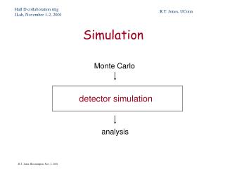
Simulation Types • Behavioral (chapter 4) • Pre-synthesis Verilog code • Timing in the behavioral code doesn’t synthesize • Gate-level(chapter4) • Structural circuits with behavioral models for each cell • Zero-delay or unit-delay per gate • Switch level (chapter 4) • Structural circuits with transistor-level cell circuits • Zero delay or unit delay per transistor • Spice (Analog / Spectre) (chapter 6) • Mixed analog/digital (chapter 6) • Config views and SpectreVerilog simulation • Performance Verification (covered next semester)
Behavioral Simulation • Pre-synthesis Verilog code, System-C, … • Integrated with composer, or command-line • verilog-xl – 1995 syntax • nc_verilog – 2001 syntax • Good for debugging functionality • If you include timing in the Verilog file this can be a little more realistic, but remember that timing doesn’t synthesize...
Switch-level simulation • Post-synthesis structural Verilog • Take “behavioral” out of the “netlist these views” box • Then you expand all the way to transistors (functional views)
Switch-level timing • Depends on where you got your nmos and pmos cells from • UofU_Analog_Parts: unit (0.1) delay on each transistor • NCSU_Analog_Parts: 0 delay on each transistor • You can use the library manager to switch from UofU to NCSU for the whole library...
Gate-level simulation • Post-synthesis structural Verilog • Uses behavioral (Verilog) models of each cell • If you have specify blocks in your behavioral cell views, then you get unit delay timing
Specify Blocks module nand2 (Y, A, B);output Y;input A;input B; nand _i0 (Y, A, B); specify(A => Y) = (1.0, 1.0);(B => Y) = (1.0, 1.0);endspecify endmodule
Specify Blocks module nand2 (Y, A, B);output Y;input A;input B; nand _i0 (Y, A, B); specify(A => Y) = (1.0, 1.0);(B => Y) = (1.0, 1.0);endspecify endmodule This default timingcan be replaced by extracted timing fromSoC. The extracted timingis from a .sdf file.
Specify Blocks module nand2 (Y, A, B);output Y;input A;input B; nand _i0 (Y, A, B); specify(A => Y) = (1.0, 1.0);(B => Y) = (1.0, 1.0);endspecify endmodule (CELL (CELLTYPE "NAND") (INSTANCE U21) (DELAY (ABSOLUTE (IOPATH A Y (0.385:0.423:0.423) (0.240:0.251:0.251)) (IOPATH B Y (0.397:0.397:0.397) (0.243:0.243:0.243)))))
sdf timing • Extract an sdf file from SoC after final routing has finished (correctly) • Timing -> ExtractRCTiming->CalculateDelay Save capacitance in a .cap file Save delays in a .sdf file
Using sdf timing • Simple – just add the sdf file name to the verilog simulation dialog box
Spice (Analog / Spectre) • The most detailed, and time consuming • Models the analog behavior of the transistors so it’s very accurate • It’s also very cumbersome on large circuits • Generating inputs is much easier in Verilog testbenches...
Mixed analog/digital simulation • A great way to go if you’re concerned about timing for a specific module • generate config view of overall circuit • use gate- or switch-level simulation on the whole thing • Then identify parts inside the circuit you want to use spectre on • resimulate using mixed SpectreVerilog simulation
Mixed considerations • You still have all the same choices for the Verilog portion of your simulation • behavioral / gate / switch level simulation • Unit or zero delay for Verilog part • You can look at the spectre part of the simulation using waveforms, or digital downstream data
Chip-level simulation • You should simulate your core as carefully as you can • Remember to make testbenches self-checking! • When you assemble your core into the pad frame • Name the pads the same thing that you had named your core signals • re-use the core testbench, but this time at the pads! • You can still use mixed mode and make some parts Spectre simulations if you like!