Download
1 / 10
170 likes | 308 Views
HPT001.014F Revision 0 Slide 1 of 10. Pressurized Water Reactor. HPT001.014F Revision 0 Slide 2 of 10. Pressurized Water Reactor Flow. HPT001.014F Revision 0 Slide 3 of 10. Primary Cooling Cycle. Reactor – heat from fission is transferred to coolant

E N D
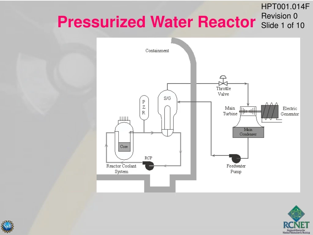
HPT001.014F Revision 0 Slide 1 of 10 Pressurized Water Reactor
HPT001.014F Revision 0 Slide 2 of 10 Pressurized Water Reactor Flow
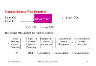
HPT001.014F Revision 0 Slide 3 of 10 Primary Cooling Cycle • Reactor – heat from fission is transferred to coolant • Steam Generators (tube side) – hot reactor coolant is circulated through tubes to produce steam • Reactor Coolant Pumps – circulate the coolant through the system
HPT001.014F Revision 0 Slide 4 of 10 Secondary Cooling Cycle • Steam Generators (shell side) – converts water to steam • Turbines – convert steam to mechanical work • Main Condenser – receives exhaust steam • Moisture Separators/Reheaters – remove moisture, reheat steam • Secondary Side Pumps – return the condensed steam to the steam generators
HPT001.014F Revision 0 Slide 5 of 10 Tertiary Loop • Cools and condenses the steam exhausted from the turbines • Transfers heat from the steam to the river
HPT001.014F Revision 0 Slide 6 of 10 PWR Design • Water on primary side is maintained at ~2235 psig to prevent boiling • Primary side water does not come into contact with secondary side water • Steam generator is the component that divides the primary side from the secondary side
HPT001.014F Revision 0 Slide 7 of 10 Plant Layout • Containment Building – contains primary cooling loop, isolates radioactive water from the environment • Auxiliary Building – contains all other potentially radioactive systems • Control Building – houses main control room, cable room, aux. instrument room, computer room, and battery room • Turbine Building – contains secondary system • Additional Equipment Building – ice making equipment
Fuel Cladding Reactor Coolant System Pressure Boundary Containment Vessel HPT001.014F Revision 0 Slide 8 of 10 Fission Product Barriers
HPT001.014F Revision 0 Slide 9 of 10 Containment Structure • Containment consists of a steel containment vessel and separate shield building • Annulus is between the two structures • Design internal pressure is 12 psig • Containment structure is last barrier against fission product release to the environment
HPT001.014F Revision 0 Slide 10 of 10 Modes of Operation • Mode 1, Plant Operation >5% > 350 ºF • Mode 2, Startup < 5% > 350 ºF • Mode 3, Hot Standby 0% > 350 ºF • Mode 4, Hot Shutdown Tavg between 200 ºF and 350 ºF • Mode 5, Cold Shutdown < 200 ºF • Mode 6, Refueling < 140 ºF • No Mode, no fuel in the core