Download
1 / 28
290 likes | 401 Views
CPE 232 Computer Organization MIPS Arithmetic – Part II. Dr. Iyad Jafar Adapted from Dr. Gheith Abandah slides http://www.abandah.com/gheith/Courses/CPE335_S08/index.html. Shift Operations. Shifts move all the bits in a word left or right sll $t2, $s0, 8 #$t2 = $s0 << 8 bits

E N D
CPE 232 Computer OrganizationMIPS Arithmetic – Part II Dr. Iyad Jafar Adapted from Dr. Gheith Abandah slides http://www.abandah.com/gheith/Courses/CPE335_S08/index.html
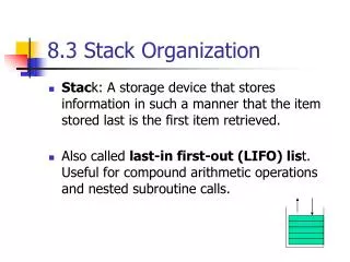
Shift Operations • Shifts move all the bits in a word left or right sll $t2, $s0, 8 #$t2 = $s0 << 8 bits srl $t2, $s0, 8 #$t2 = $s0 >> 8 bits • Notice that a 5-bit shamt field is enough to shift a 32-bit value 25 – 1 or 31 bit positions • Such shifts are logical because they fill with zeros
Shift Operations, con’t • An arithmetic shift (sra) maintain the arithmetic correctness of the shifted value (i.e., a number shifted right one bit should be ½ of its original value; a number shifted left should be 2 times its original value) • so sra uses the most significant bit (sign bit) as the bit shifted in • note that there is no need for a slawhen using two’s complement number representation sra $t2, $s0, 8 #$t2 = $s0 >> 8 bits • The shift operation is implemented by hardware separate from the ALU • Using a barrel shifter: is a digital circuit that can shift a data word by a specified number of bits in one clock cycle ! • Simply a set of multiplexers multiplexers !
Shift Operations – Barrel Shifter D0 D3 D2 D1 Example : 4-bit barrel shifter (rotate to the left) Y0 D1 D0 D3 D2 Y1 4-bit Barrel Shifter D Y 4 4 D2 D1 D0 D3 Y2 S0 S1 D3 D2 D1 D0 Y3 S1 and S0 determine the shift amount 0,1,2, and 3
Multiply • Binary multiplication is just a bunch of left shifts of the and adds • Size of product is 2n. 4 bits 4 bits Partial Products 8 bits
Multiplication Hardware • Hardware implementation of multiplication algorithm • Operation • Initialize the lower 32 bits of the multiplicand register with the multiplicand • Initialize the product register to 0. • If the multiplier LSB is 1, add multiplicand to product • If the multiplier LSB is 0, don’t add • Shift multiplicand left and multiplier right by one bit • Repeat 32 times
Multiplication Hardware • Flowchart for multiplication algorithm • If each step takes one cycle, we need almost 100 cycles for 32 bit multiplication • Check the multiplication example in page 180 for better understanding !
Optimized Multiplication Hardware • ALU and multiplicand register are both 32 bits wide • Multiplier register is omitted and multiplier is placed in the lower 32 bits of the product register • The product register is shifted to the right along with the multiplier register until we have 32 repetitions
Fast Multiplication Units • Use 31 32-bit adders to compute the partial products • One input is the multiplicandANDedwith a multiplier bit and shifted to the left by 1, and the other is the partial product from previous step. • Example: show the multiplication tree to compute 5 X 3. Assume unsigned numbers represented using 3 bits.
Multiplication - Notes • Multiplies are done by fast, dedicated hardware and are much more complex and slower than adders • Multiplication by power of two can be performed by simple left shifts in hardware. It is the compiler responsibility to choose when to use left shifts for multiplication by power of 2 in order to reduce the execution time • Signed multiplication can be performed in similar manner. Convert the multiplicand and the multiplier to positive numbers (if necessary), then determine the product sign from their signs. What is the logic required to compute the sign of the product ?
MIPS Multiply Instructions • Multiply produces a double precision product mult $s0, $s1 # hi||lo = $s0 * $s1 multu $s0, $s1 # hi||lo = $s0 * $s1 • Low-order word of the product is left in processor register loand the high-order word is left in registerhi • Instructionsmfhi rd andmflo rd are provided to move the product to (user accessible) registers in the register file • Both instructions ignore overflow; it is the responsibility of the software to check if the result fits into 32 bits ! • For multu, there is no overflow if hi is 0 • For mult, there is no overflow if hi is the replicated sign of lo rt rs
Division • Division is just a bunch of quotient digit guesses and left shifts and subtracts • Dividend = Quotient x Divisor + Remainder
Division Hardware • Division algorithm • Divisor is placed in the upper 32 bits and dividend is placed in the lower 32 bits of the remainder register
MIPS Divide Instruction • Divide generates the reminder in hi and the quotient in lo div $s0, $s1 # lo = $s0 / $s1 # hi = $s0 mod $s1 div u $s0, $s1 • Instructionsmfhi rd andmflo rd are provided to move the quotient and reminder to (user accessible) registers in the register file • As with multiply, divide ignores overflow so software must determine if the quotient is too large. • Software must also check the divisor to avoid division by 0. rs rt
Divide - Notes • Signed division • Remember the signs of the dividend and divisor and use to determine the sign of the quotient • The sign of the remainder is always the same as the dividend (Check by yourself the division of 5/2 using different combinations of the signs of the dividend and the divisor) • Fast division algorithms use look-up tables to guess several quotient bits per step. The algorithms rely on subsequent steps to correct wrong guesses • The Pentium bug in 1994 • Cost for recall was about $500M
Representing Big (and Small) Numbers • How to encode real numbers ? • 4,600,000,000 or 4.6 x 10⁹ • 0.0000000000000000000000000166 or 1.6 x 10⁻²⁷ • There is no way we can encode either of the above in a 32-bit integer. • Floating point representation (-1)sign x F x 2E • Still have to fit everything in 32 bits (single precision) • Normalized representation (no leading zeros and one bit to the left of binary point) • More bits in the fraction (F) or the exponent (E) is a trade-off between precision (accuracy of the number) and range (size of the number) • Smallest number 2.0x10-38 and largest is 2.0x1038
Representing Big (and Small) Numbers • Overflow and underflow ! • Double precision format (use 64 bits instead of 32) • Smallest number 2.0x10-308 and largest is 2.0x10308 • Most computers these days conform to the IEEE 754 floating point standard • To pack more bits into the significand, one bit of the normalized binary numbers is implicitly assumed 1 • Since 0 has no leading 1, it has a reserved exponent value of 0 so that hardware won’t attach 1 to it
Representing Big (and Small) Numbers • Special numbers in the IEEE standard
IEEE 754 FP Standard Encoding • This representations is intended to simplify sorting of floating numbers using integer comparison • Separate sign bit (sign and magnitude notation) • Placing the exponent before the significand • Use of biased exponent notation; add a constant value to represent all exponents with positive numbers • In single precision, bias is 127 • Exponent -3 is represented as -3 + 127 = 124 • Exponent 5 is represented as 5 + 127 = 132 • While in double precision , the bias is 1023 • So in biased notation, the decimal value represented by the normalized floating-point number is (-1)S x (1+Fraction) x 2(Exponent – Bias)
Floating-point Example • Example 1: Show the IEEE754 representation of -0.75 using single and double precision formats • (0.75)ten = (0.11)two • (-0.75) ten = (-0.11)two (we use sign and magnitude) • in binary scientific notation -0.11two x 20 • in normalized binary scientific notation -1.1two x 2-1 • add the bias to the exponent • In single precision add 127 -1.1two x 2126 • In double precision add 1023 -1.1two x 21022 • convert the exponent into binary • 126 = (01111110)2 • 1022 = (01111111110)2 • drop the 1 on the left of the binary point and fill the corresponding fields
Floating-point Example • Example 1: Show the IEEE754 representation of -0.75 using single and double precision formats • Single precision • Double precision
Floating-point Example • Example 2: What decimal number N is represented by the following float ? N = (-1)S x (1+Fraction) x 2(Exponent – Bias) = (-1)1 x (1+0.25) x 2(129 – 127) = -1 x 1.25 x 22 = -1.25 x 4 = -5
Floating Point Addition • Analogy to adding floating decimals (Example: 9.999x101 + 1.610 x 10⁻¹using four digits) • Steps to perform (F1 2E1) + (F2 2E2) = F3 2E3 • Step 1: Restore the hidden bit in F1 and in F2 • Step 1:Align fractions by right shifting F2 by E1 - E2 positions (assuming E1 E2) • Step 2:Add the resulting F2 to F1 to form F3 • Step 3:Normalize F3 (so it is in the form 1.XXXXX …) and check for overflow/underflow in the exponent • Step 4:Round F3 and possibly normalize F3 again • Step 5:Rehide the most significant bit of F3 before storing the result
Floating Point Addition • Example: show how to add 0.625 and -0.125 using floating point binary representation • In normalized scientific notation this is equivalent 1.100 x 2-1 + -1.000 x 2-3 • Align exponents 1.100 x 2-1 + -0.010 x 2-1 • Add significands 1.010 x 2-1 • Normalize the sum (if necessary) and check for overflow/underflow • Round the sum and normalize again
Accurate Arithmetic • In arithmetic we are restricted with the number of bits. Thus we may need to truncate the operand with smallest power to fit into the available bits • IEEE754 standards define two extra bits to the right of the numbers; the guard and round bits. • Decimal example: 2.56 x 100 + 2.34 x 10² • Assume significand is represented in 3 digits only • Without guard and round digits (truncation occurs for two digits) (2.34 + 0.02) x 102 = 2.36 x 10² • With guard digit, we don’t have to truncate the small number when shifted to the right to match the large number (2.3400 + 0.0256) x 102 = 2.3656 x 102 = 2.37 x 10² (after rounding) • Sticky bit !
MIPS Floating Point Instructions • MIPS has a separate Floating Point Register File($f0, $f1, …, $f31) (whose registers are used in pairs for double precision values) with special instructions to load to and store from them lwc1 $f1,54($s2) #$f1 = Memory[$s2+54] swc1 $f1,58($s4) #Memory[$s4+58] = $f1 • And supports IEEE 754 single add.s $f2,$f4,$f6 #$f2 = $f4 + $f6 and double precision operations add.d $f2,$f4,$f6 #$f2||$f3 = $f4||$f5 + $f6||$f7 similarly forsub.s, sub.d, mul.s, mul.d, div.s, div.d
MIPS Floating Point Instructions, Con’t • And floating point single precision comparison operations c.x.s $f2,$f4 #if($f2 x $f4) cond=1; else cond=0 where x may beeq, neq, lt, le, gt, ge and branch operations bclt 25 #if(cond==1) go to PC+4+100 bclf 25 #if(cond==0) go to PC+4+100 • And double precision comparison operations c.x.d $f2,$f4 #$f2||$f3 x $f4||$f5 cond=1; else cond=0