Download

1 / 49
500 likes | 644 Views
...At the 1st of May, when the church-bell hath rung, it was a sign in the Sun: for one hour or more the stars were seen in the sky and the Sun became like a crescent with bright flames coming from its horns… 1185AD Russian chronicles.

E N D
...At the 1st of May, when the church-bell hath rung, it was a sign in the Sun: for one hour or more the stars were seen in the sky and the Sun became like a crescent with bright flames coming from its horns… 1185AD Russian chronicles »… Месяца Майя в 1 день, в звонение вечернее, бысть знамение в солнци: морочно бысть вельми, яко на час и более, и звезды виде-ти, и человеком воочию яко зелено бяше, и в солнци учинися яко месяц, из рог его яко угль жаров исхожаше: страшно бе видети человеком знаменье божие ..." 1185 AD Угль жаровъ -- въ Лаврентьевской и в рукоп. Татищева.Угль горящь -- въ ТверскойОгнъ жарящий -- въ Новгородской II.Огнь горяший -- въ Псковской I.Огнь палящий -- въ Никоновской Даниил Осипович Святский "Астрономические явления в русских летописях" (Петроград, 1915) с приложением М.А.Вильева "Канона русских затмений" (с 1060 по 1705 г.),
Observation of the Suprathermal Electrons during Magnetic Reconnection in Tokamaks P.V.Savrukhin with contribution from E.J.Strait2, A.V.Sushkov1, S.V.Tsaun1, V.M.Trukhin1 INFM, Politecnico di Torino, Italy 1RRC Kurchatov Institute, Moscow, Russia 2General Atomic, San Diego, USA
Outline • Introduction (motivation of the experiments) • Experimental setup - diagnostic techniques used for studies of the non-thermal electrons in tokamaks (x-ray & ECE) • Experimental studies generation of the suprathermal electrons (Eg~25-100keV) around X-point of the magnetic islands • Modelling of the suprathermal electrons induced during magnetic reconnection (simplified view) • Summary
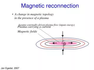
Non-thermal electrons and magnetic reconnection Acceleration of electrons to suprathermal energies, Eg~100keV, is one of the typical feature of magnetic reconnection in variety of plasma phenomena ranging from large-scale astrophysics events to energy relaxations and disruptions in laboratory experiments. The non-thermal electrons could be connected with strong electric fields, shock waves, and plasma turbulence induced during topological rearrangement of magnetic fields and plasma flows during reconnection. The mechanisms are still arguing in the theory.
Non-thermal electrons in tokamak: The non-thermal electrons can be especially important during disruption instability in high-temperature collisionless plasma in tokamaks, when electron acceleration represents one of the dominant mechanism of current dissipation in the reconnection layer. Runaway electrons are observed in previous experiments in tokamaks in plasma with low density and during major disruptions: Pulsator [Fussmann,1979], PLT [Barnes,1981], T-10 [Volkov,1990], PBX‑M [VonGoeller,1996], TEXTOR [Jaspers,1996], JT-60 [Yoshino,1997], DIIID [Evans,1998], Tore Supra [Peysson,1999], JET [Gill,2000] …etc
“Classical” hard x-ray bursts during density limit disruption observed with conventional x-ray arrays SXRA 25855 Sxra11 T-10 Time , ms 2,1 & 1,1 modes x-ray contour plot Rail Limiter Time , ms radiation from the limiter no direct connection with reconnection
“…Extensive experimental and theoretical studies have identified physics basis of runaway formation, loss and wall interaction in both present and reactor scale tokamaks…” [ITER Physics Summary, Nuclear Fusion,1999] MHD modes are generally considering as an effective loss mechanism of the RA electrons: tloss kt (dB/Bt)-2 dNr /dt= ne /tdr + Nr /tav – Nr /tloss
“Classical” hard x-ray bursts during density limit disruption SXRA Narrow spots at the limiter can indicate filament-like structure of the beams - possibly connected with MHD modes? [see Gill,2000] 25855 Sxra11 T-10 2,1 & 1,1 modes radiation from the limiter Rail Limiter
Filament-like structures connected with the m=1,n=1 magnetic island are observed in TEXTOR Entrop,1999, Jaspers 2000 pellet injection RA electrons are lost from the background plasma and accumulated inside the m=1,n=1 island Image of synchrotron emission in “classical” plasma with low density - no filaments Sweep 60 Hz
Magnetic islands play a role in determining the structure of the runaway beams. Do we have adequate diagnostics for reliable identification of the localized suprathermal electrons beams in a tokamak plasma?
Standard x-ray imaging systems, generally used for soft x-ray measurements in direction orthogonal to the plasma column, are insensitive to suprathermal electrons with x-ray emission in limited forward cone along the lines of flight Limited time and spatial resolution of measurements of the non-thermal x-ray emission tangential to the helical field lines in previous experiments [PLT,PBX-M] Requirements: tangential view, dt~10msec, dr/aL~0.03-0.05 - Tangential array in T-10
Outline • Introduction (motivation for the experiments) • Experimental setup - diagnostic techniques used for studies of the non-thermal electrons in tokamaks (x-ray & ECE) • Experimental studies (generation of the suprathermal electrons (Eg~25-100keV) around X-point of the magnetic islands • Modelling of the suprathermal electrons induced during magnetic reconnection (simplified view) • Summary
T-10 tokamak (R=1.5,a=0.3m) • tangential x-ray array silicon and CdTe XRP (1), • standard x-ray tomographic arrays XRA (2), XRB (3), XRC (4), • x-ray matrix array XRM (5), • x-ray proportional counter XWD (6), • sets of CdTe detectors (7). • NaI(Tl) monitor (8) and • Ge PHA system (9). Tangential view (simulation)
Outline • Introduction (motivation for the experiments) • Experimental setup - diagnostic techniques used for studies of the non-thermal electrons in tokamaks (x-ray & ECE) • Experimental studies (generation of the suprathermal electrons (Eg~25-100keV) around X-point of the magnetic islands • Modelling of the suprathermal electrons induced during magnetic reconnection (simplified view) • Summary
RADIATIVE DENSITY LIMIT DISRUPTION IN T-10 OHMICALLY HEATED PLASMA Additional gas puff Enhanced radiation at the plasma edge Te(r) erosion 2/1&1/1 modes Energy quench Loop voltage growth HXR burst runaways Hard x-ray burst`-> At start-up and 5ms AFTER the energy quench
x-ray bursts are observed with tangentially viewing x-ray array - coinciding with rotation of the 2/1 mode tangential x-ray array Suprathermal electrons? Standard radiation due to RA interaction with the wall? conventional (orthogonal) x-ray arrays observed with all x-ray arrays Standard hard x-ray burst during disruption
Classical sawteeth in ohmically heated plasma with high density <ne> ~ 4.5 1019m-3 and high safety factor qa ~ 3.5 T10-26087 xray7 3 2 1 SAWTEETH Energy quench see expanded view 730 740 750 760 Time , (ms)
X-ray contour plots measured using vertical (XRA) array Contour lines in the centre (|R‑R0|<3-5cm) are not shown in the figure due to high level of the x-ray intensity (see dashed area).
X-ray measurements in toroidal direction indicate intensive spikes observed simultaneously with rotating m=1,n=1 mode during a sawtooth crash T-10 tangential x-ray array spike m=1,n=1 mode
The x-ray spikes (superimposed with the m=1 mode) have maximum amplitude around the q=1 surface (sawtooth inversion surface r=rs). sawtooth crash spike Radial profiles of the x-ray perturbations during the non-thermal spikes (1) and sawtooth crash (2).
The x-ray spikes are displaced radially after the crash schematic view
spike Time,ms The non-thermal x-ray spike rotates with the m=1 mode a14 The non-thermal x-ray spike (rotating with the m=1 mode in clockwise direction) is observed consecutively along chords with various pitch angle starting starting from the equatorial mid-plane: q 0o (a14), q -60o (b7), q -120o (c6), q -180o (a5), q -240o (b14). b7 b14 a5
Enhanced amplitude of the spikes measured with the tangential x-ray array indicate nonthermal origin of the radiation Tomographic X-ray images in T-10 are phenomenologically similar to the Kadomtsev reconnection The spikes could be connected with localized beams of the non-thermal electrons around X-points (lines) of the m=1,n=1 magnetic island BUT DO WE HAVE THE RECONNECTION ???
RECONNECTION AT THE SAWTOOTH CRASH Magnetic fields in tokamaks are measured using Motional Stark Effect Method First demonstrated on PBX-M // F.M Levinton, et al., PRL,1989 - TFTR // M.Yamada, et al., RSI,1992 - DIII-D // D.Wroblewski, et al., RSI,1990, B.W.Rice, et al., PRL,1997 TFTR’92 TEXTOR’95 safety factor , q(0) TEXTOR’86 q0 = 0.8 - 1.0 MSE DIIID Heidbrink,NF’99 Year
DIAGNOSTIC TECHNIQUE -DIIID • DIII-D tokamak - reconstruction of the internal magnetic fields: • MSE measurements • (dr~5cm, dt=2ms) [3] • EFIT code [4] - equilibrium • magnetic surfaces • external magnetic field • measurements [5]. MSE diagnostic is based on measuring the polarization angle of light emission from neutral atoms experienced large Lorentz electric field EM=vb x B due to their motion across the plasma magnetic field. B.W.Rice, et al., fusion.gat.com
DIAGNOSTIC TECHNIQUE -DIIID w=nwce(1-(vr/c)2)1/2 • Non-thermal bursts and MHD perturbations: • multi-array x-ray imaging systems (dr=3cm, dt=0.01msec) [2] • second harmonic x-mode ECE radiometer (dr=2.5cm , dt=0.01ms)[1] B w=nwce wce=eB/mc w wce R Rec 31 radial (frequency) channels
SAWTEETH DURING NBI & RF HEATING Fig.1 DD plasma upper-single null configuration Bt=1.9T Ip=1.2MA k95=1.7 Pnb=2.8MW (Enb=80keV) Prf=1.0MW (f=60MHz) [7] Heidbrink, 1999
ECE BURSTS DURING SAWTOOTH CRASH ECE bursts: • are observed during the last cycle of the m=1 mode • are placed around and just outside the sawtooth inversion radius (q=1 surface) at the low-field side of the torus
ECE bursts - non-thermal ? DWout = 2.5 DWin
DELAY OF THE BURSTS AT OUTER RADII ECE perturbations appear to be displaced by Dr<~10 cm in respect to the x-ray perturbations due to relativistic frequency shift: w=w2ce(1-(vr/c)2)1/2 Burst are connected with non-thermal electrons with energies Eg 30-40 keV Burst displacement: • Dr/Dt (1‑2)104m/s • 10 times faster than “normal” heat pulse
X-RAY BURST AND THE m=1 MODE x-ray intensity measured along chords tangential to the q=1 surface q 30o q -30o q -120o q -240o The x-ray bursts coincides with localisation of maximum perturbation due to the m=1 mode
BURST AT THE X-POINT OF THE m=1 ISLAND Simulations of the chord-integrated x-ray intensity: • uniformly rotating m=1 mode (solid displacement of the plasma core) • bright “ribbon”-like structure around the q=1 surface The bursts can be associated with position of the X-point (line) of the magnetic island
MAGNETIC PERTURBATIONS AT THE CRASH Safety factor profiles q(r) are determined from the measured MSE pitch angle (amse) and EFIT calculations Amplitude of the electric field induced during the reconnection can be estimated from rate of change of the perturbed helical magnetic flux around the q=1 surface E ~ (1-q0)r1Bp1 / 4tcrash tcrash ~ 0.05ms E~50V/m [6] Wesson, 1990
INCREASE OF THE BURSTS WITH Dq(0)/tcrash ( ) Maximum amplitude of the ECE bursts (DTburst) is observed in the experiments with strong modification of the internal magnetic fields during the crash (see, marks t1,t2,t3 in Fig.1 and TABLE.1) () Calculated density of the non-thermal electrons (Nr1max) is increased in plasma with strong induced electric fields (E1max) (***) Vertical double lines mark smaller bursts observed in similar plasma conditions.
Outline • Introduction (motivation for the experiments) • Experimental setup - diagnostic techniques used for studies of the non-thermal electrons in tokamaks (x-ray & ECE) • Experimental studies (generation of the suprathermal electrons (Eg~25-150keV) around X-point of the magnetic islands • Modelling of the suprathermal electrons induced during magnetic reconnection (simplified view) • Summary
MHD modes can drive the non-thermal electron beams due to strong induced electric fields, E1~10 - 100 V/m Schematic view of the mechanisms leading to generation and loss of the non-thermal electrons in a tokamak plasma in presence of the magnetic flux perturbations dY (MHD modes).
Calculations of the runaway production rate depends critically on amplitude of the electric field generated during the reconnection. Detailed calculations of the field require 3‑D MHD&kinetic simulations, which are complicated in real experimental conditions. In a simplified way, longitudinal electric field induced during the sawtooth crash around the q=1 surface can be estimated from calculation of the inductive response to reduction of the helical magnetic flux during a sawtooth crash 1983 Gurevich, Dimant, Dnestrovskij, Kostomarov, SmirnovDy=1-3 10-3 Vsec, E ~ 30V/m 1990 Wesson, NF30, 2545 E~(1-q0)r1Bp1/(4tcrash), E ~ 15V/m
NONTHERMAL ELECTRONS - MODELING dNr/dt = ne/tdr + Nr/tav – Nr/tloss tdr-1 0.3 need -3(Zeff+1)/16 exp (-1/4ed - ([Zeff+1]/ed)1/2) ed=E/Ec Ec=e3neZefflnL/(4pe02mevth2) tav-1 eE / 2meclnLa(Zeff) tloss–1 Dm /dr2 Dm (pR0qvr)(dB/Bt)2 dr~w1 dB/Bt=s1w12/(16r1(R0+r1)) E ~ (1-q0)r1Bp1 / 4tcrash
TABLE I. Plasma parameters used in the simulations of the non-thermal electrons 1st crash NB NB&RF Radius of the q=1 surface, r1,m 0.20 0.20 0.24 Crash time, tcrash, ms 0.15 0.10 0.05 Safety factor changes, Dq0, r.u. 0.04 0.06 0.17-0.2 Induced electric field, E1, V/m 3 7 50 Electron temperature, Te1 , keV 2.1 2.0 1.9 Electron density, ne1, 1019 m-3 2.8 2.9 3.3 Dreicer field , Ec , V/m 5.1 5.6 6.7 Magnetic shear, s1, r.u. 0.8 0.8 0.8 Non-thermal density, Nr1max, 1017m-3 2.5 4.5 8.5
NONTHERMAL ELECTRONS - SIMULATION growth of the electric field (E1) up to E1max ~ 50V/m during a sawtooth crash (t~ 2031.06-2031.11msec) generation of the runaway beam with density up to Nr1max ~ 8.5 1017 m-3 around the q=1 surface see TABLE.1 Simulated evolution of the electron beams agrees qualitatively with temporal behavior of the ECE bursts observed in the experiments
INCREASE OF THE BURSTS WITH Dq(0)/tcrash ( ) Maximum amplitude of the ECE bursts (DTburst) is observed in the experiments with strong modification of the internal magnetic fields during the crash (see, marks t1,t2,t3 in Fig.1 and TABLE.1) () Calculated density of the non-thermal electrons (Nr1max) is increased in plasma with strong induced electric fields (E1max) (***) Vertical double lines mark smaller bursts observed in similar plasma conditions.
Outline • Introduction (motivation for the experiments) • Experimental setup - diagnostic techniques used for studies of the non-thermal electrons in tokamaks (x-ray & ECE) • Experimental studies (generation of the suprathermal electrons (Eg~25-150keV) around X-point of the magnetic islands • Modeling of the suprathermal electrons induced during magnetic reconnection (simplified view) • Summary
Summary - characteristics of the beams: Localization: Dr/r1 ~ 0.02-0.2, Dq ~ 30o ribbon Reconnection rate: Dq(0)/Dtcrash ~ 0.5 - 4 ms-1 Energy of the beams: Єg ~ 30-100keV Єg ~ (E1* 2pR0) * tcrash / (2pR0 /vr) ~ 100keV Density of the beam up to Nr~ 8 1017m-3 ne~ 3 1019m-3 Can drive transient plasma currents (of order of IRA ~ 10-20 kA) during sawtooth crash
Conclusions. • Non-thermal x-ray and ECE bursts observed during sawtooth crashes in T-10 and DIII-D tokamaks can be connected with suprathermal (Eg~25-100 keV) electron beams induced during magnetic reconnection around X-point of the m=1,n=1 magnetic island. • Production rate and losses of the non-thermal beams depend critically on rate of the reconnection Dq(0)/tcrash and amplitude of the MHD perturbations.
ACKNOWLEDGMENTS The authors would like to thank W.W.Heidbrink, T.E.Evans, E.A.Lazarus, S.V.Mirnov, B.W.Rice, S.VonGoeller, F.M.Stefanovskij, and R.J.Hastie for stimulating discussions. The first author would like to thank General Atomic for hospitality during his visit to the Laboratory. The work was supported in part by Russian Fund of Basic Research (Grants RFBR-00-02-16768 and RFBR- 98-02-17382) and the U.S. Department of Energy under Contract No. DE-AC03-99ER54463..
Quasi-coherent radiation induced by the non-thermal electrons during magnetic reconnection in T-10 tokamak P.V.Savrukhin RRC «Kurchatov Institute», Moscow, Russia Poster to be presented at EPS Conference in St.Petersburg, July, 2003 Report to be submitted to IAEA TCM on High Energy Particles in Plasma, San Diego, October, 2003 RFBR (01-02-16768) MINATOM
Modulation of the magnetic field in tokamak can be connected, for example, with helical eddies due to interaction of the neighboring MHD modes and variety of stray fields, arisen from imperfect alignment of a tokamak magnetic system. In particular, strong field modulation can be produced by the magnetic ripples due to discrete number of the toroidal field coils (see Fig.1a).
Movement of the electrons trough the magnetic ripples leads to modulation of the beams and can be accompanied by induced radiation [6,7].
In an international collaboration, a new accelerator project is being developed and planned at the DESY research center in Hamburg. This project is known as TESLA. TeV-Energy Superconducting Linear Accelerator / 33-kilometer-long - collisions between particles of the highest energies - source of intense and extremely short X-ray flashes with laser properties. The research and application areas range from the structure of matter and its creation in the big bang to research into materials and the processes of life.