Download
1 / 28
300 likes | 440 Views
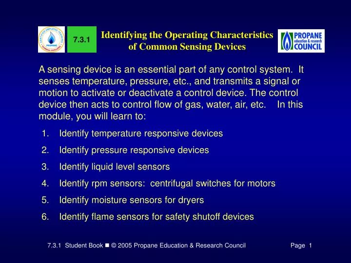
7.3.1. Identifying the Operating Characteristics of Common Sensing Devices.

E N D
7.3.1 Identifying the Operating Characteristics of Common Sensing Devices A sensing device is an essential part of any control system. It senses temperature, pressure, etc., and transmits a signal or motion to activate or deactivate a control device. The control device then acts to control flow of gas, water, air, etc. In this module, you will learn to: • Identify temperature responsive devices • Identify pressure responsive devices • Identify liquid level sensors • Identify rpm sensors: centrifugal switches for motors • Identify moisture sensors for dryers • Identify flame sensors for safety shutoff devices
Figure 1. Bimetals Deflect When Heated Because of the Different Rates of Expansion of the Two Metals Identifying temperature responsive devices In most gas appliances there is a need to control temperature, such as the temperature of circulating air in a furnace, or of stored water in a water heater, or the temperature inside a range oven.A number of sensing devices are used to control operating temperatures. Possible Diagram Symbol Bimetals A bimetal consists of two strips of different metals fastened together along their entire length.
Figure 3. Bimetal Disc Snaps When Temperature Changes Figure 2. U-Shaped Bimetal Deflects When Heated
4a. Combination Limit & Fan Control 4b. Wall Thermostat Figure 4. Operation of Bimetal Helix and Spiral Bimetal Coils Another commonly used bimetal type sensor is a bimetal coil. In this type of sensor two strips of different metals are fastened together, formed into a coil, and anchored at one end. The twisting type bimetal is often used to activate a control such as a furnace limit/fan control, while the coil form is frequently used in room thermostats.
Unevenly heated shapes In the single metal differential expansion sensor the “hot” leg and “cold” leg are fastened together, and anchored firmly to an immovable support. The hot leg is heated to a greater degree than the cold leg, and expands more than the cold leg. As a result the free end of the sensor element moves as shown in Figure 5. This movement is used to activate a control. A common use of uneven heating of single metal legs has been used in automatic gas pilots. Figure 5. Single Metal Temperature Sensor Deflects Because of Uneven Heating of Legs
Figure 6. Rod and Tube Temperature Sensor Rod and tube sensors The rod is fastened firmly to the inside of the closed end of the tube (the right in Figure 6) and its other end is free to move. When the fluid in which the rod and tube is immersed is cooled the tube shortens, and the rod remains at its original length. The free end of the rod then moves to the left as shown in Figure 6. This motion of the rod is used to actuate a control. Perhaps the most common use of rod and tube sensors is in storage water heater thermostats.
Figure 7. Hydraulic or Pneumatic Bulb Sensors Rely on Expansion of Confined Fluid to Actuate Controls Hydraulic and pneumatic bulbs Liquids and gases expand when they are heated and contract when they are cooled. If these liquids or gases are contained in a closed container or system, they cause a rise in pressure. These pressure variations with temperature change can be used to actuate controls. Hydraulic and pneumatic temperature sensors are often used in range oven thermostats, furnace limit controls, and space heater temperature controls.
A resistor normally reduces current flow as it gets hotter. A thermistor acts in the opposite way—it increases current flow as its temperature increases. Electrical resistance coils and thermistors Resistance coil and thermistor sensors are used in electrical control circuits to control current flow in the circuit to activate or deactivate controls. This control of current, in turn, depends on the electrical resistance of the coil or thermistor, which varies with temperature.
Fusible links Possible Diagram Symbol Sometimes under adverse operating conditions, combustion products may spill from the combustion chamber into another section of an appliance. In some appliances a fusible link is connected by a wire in the gas control circuit located just outside the combustion chamber. If flames or hot gases roll out of the combustion chamber, the fusible link melts and breaks the circuit, shutting off power to the gas control.
Possible Diagram Symbol Identifying pressure responsive devices Other sensors used with some controls sense pressure changes caused by heating or cooling. For example, such devices are used to control or limit steam and/or water pressures in boilers, furnaces and water heaters. These sensors may take one of a number of forms.
Metallic bellows and diaphragm sensors Metallic bellows or diaphragms sense pressure changes such as occur in boilers. Figure 8. Metallic Bellows and Diaphragm Elements Convert Pressure into Linear Motion
Coiled metallic tubing Coiled metallic tubing also can be used to sense pressure changes. This type of device is known as a Bourdon tube. Figure 9. Coiled Metallic Tube Sensor (Bourdon tube)
Possible Diagram Symbol Figure 10. Sail Switch Is Actuated by Air Movement Flow sensor switches and sail switches Often it is necessary to sense the flow of air. For example, in an appliance using a blower to supply combustion air, it is important that flow of combustion air be assured before gas is allowed to flow to the burner(s).
Possible Diagram Symbol Identifying liquid level sensors Liquid level sensors are used to control the level of liquid in an appliance, such as in a boiler.
Electrical – contact type Figure 11. Electrical Contact Type Liquid Level Sensor
Float and other types A similar arrangement with a float also can be used to open or close an electrical switch, rather than the valve directly. This switch may be used to open or close an electrically operated liquid supply valve. Such a switch also can be used to shut off the gas supply to an appliance (such as a boiler) when the liquid level drops to a given level (low water cutoff). Figure 12. Float‑Type Device Controls Liquid Level
Identifying rpm sensors: centrifugal switches for motors (This illustration shows switch opening as motor runs.)Usually centrifugal switches on motors are used for switching circuits external to the motor circuit. For example, a switch may be placed in a gas control circuit to assure a blower supplying combustion air to a power burner is operating before gas is allowed to flow. Figure 13. Centrifugal Switch Opens or Closes When Motor Rotor Is Turning.
Temperature/ Moisture Sensor Diagram Symbol Temperature Sensor Diagram Symbol Identifying moisture sensors for dryers A gas dryer is essentially a cabinet containing a rotating drum, in which heated air is circulated to remove water from the clothes and dry them. Several methods are available to achieve this control over the dryness of clothes. A very accurate method has been developed that uses an enthalpy switch (senses temperature & relative humidity) and solid-state electronics.
Figure 14. Thermocouple & Gas Valve Identifying flame sensors for safety shutoff devices Thermocouple As long as the pilot flame acts to sufficiently heat the hot junction of the thermocouple, the DC current produced will act to hold open a gas control valve, allowing gas to flow to the appliance burner when gas is called for.
Bimetal Some safety shutoff devices use bimetal sensors to assure an ignition source is present. Safety shutoff devices of this type use a single metal (stainless steel) sensor element, relying on uneven heating of the two legs to open or close a switch. With a pilot flame present of sufficient size to ignite the main burner(s), the sensor causes closure of an electric switch in the circuit of an electrical valve. If the pilot flame is extinguished, the sensor acts to open this switch cutting off electrical current to the valve, which closes to shut off the gas supply to the appliance.
Figure 15. Mercury Powered Diastat Hydraulic or mercury vaporization type Other safety shutoff devices use liquid or vapor expan-sion type sensors. The flame heats the liquid in the sensor bulb. The resulting pressure buildup in the sensor system acts on a metallic bellows or diaphragm, actuating a switch or gas valve when the pilot flame is present.
Optical system— It is also possible to detect the presence of flame by optical sensors. Two such devices are the photocell and the photo resistive sensor. The photocell is an electron tube containing a light sensitive surface. When light strikes this surface it generates a small amount of electrical current. This current can then be amplified by electrical devices to operate an electric relay, which in turn controls electric current flow to an appliance control.
Figure 16. Spark Ignition Flame Rectifier Flame rectificationis used as the operating principle of ignition and burner control systems on most high efficiency residential gas furnaces and boilers. An electrical rectifier is a device, such as a diode, which allows current to flow essentially in only one direction. In other words, it converts an alternating (AC) current to a direct (DC) current. It has been found that flames possess the capability of acting as a rectifier.
Principles of Operation A single rod is placed near the pilot burner so that when the pilot is lit the rod is in the pilot flame. AC voltage is applied to the rod, and the current passes through the flame on its path to a larger electrode which is the sensor for the control circuit. The rectified DC current flowing through the flame is then used to activate an electronic relay, which in turn allows the gas valve to open as long as a pilot flame is present. There are two basic types of electronic spark ignition systems. One uses a spark to light the main burner directly. This type is commonly referred to as a Direct Spark Ignition (DSI) system. The second spark method used for residential equipment is to light a pilot which then ignites the main burner. The pilot flame must be proven before the main burner gas valve is energized. This type is known as an Intermittent Ignition Device (IID)
Figure 17. Blue Flame Structure Sensing Methods With standing pilots, heat is a necessary ingredient for proper thermocouple operation. But this is not the case with IIDs when flame conduction or rectification is used. To better understand the principles of flame conduction and rectification, it is necessary to understand the structure of gas flames. A flame is a series of small, controlled explosions, which causes the immediate atmosphere to become ionized. This ionization causes the atmosphere within the flame to become conductive. This conductive characteristic is used in flame conduction, as illustrated in Figure 18.
Figure 18. Flame Rectification With flame rectification, the flame and probes are used in a manner similar to a switch that can change the circuit from AC to DC. There are two features critical to flame rectification: • The surface area of one probe that is exposed to the flame must be greater than the area of the other probe. • The flame must be properly placed to provide the conductive path.
Figure 19. Sending the Flame Safety Signal to the Sensing Circuit Sending the Flame Signal to the Ignition Module It is the conversion to a DC milliamp signal to the ignition module that becomes the signal that switches power to open the gas control valve and keeps it open until the thermostat heat anticipator ends the “call for heat”.
Time to See If You Got the Key Points of This Module… • Complete the Review on pages 20 - 22. • See if you are ready for the Certification Exam by checking off the performance criteria on page 23.