Download

1 / 42
420 likes | 511 Views
This seminar delves into recognizing and utilizing design patterns (DPs) in software design models through logic inferences. Covering motivation, formalization, tool support, and experimental findings, the session aims to bridge existing gaps in pattern recognition to enhance software quality and productivity. Using illustrative examples and code instances, the presentation explores implementations with tools like LAMBDES-DP, Prolog, UML diagrams, and SPASS inference engines for pattern matching.

E N D
Recognition of Patterns in Software Designs Models via Logic Inferences Hong Zhu Department of Computing and Electronics Oxford Brookes University Oxford OX33 1HX, UK Email: hzhu@brookes.ac.uk
Acknowledgement This presentation is based on joint research work with • Dr. Ian Bayley of Oxford Brookes University • Dr. Lijun Shan, who was my PhD student • Mr. Richard Amphlett, who was supported by the Undergraduate Research Student Scholarship funded by the Reinvention Centre, UK. Seminar: Recognition of Patterns in Design Models
Outline • Motivation and related works • Tool support to the application of DPs • Formalisation of DPs • Our previous work • Specification of DPs • Semantics of UML models • The proposed approach • Bridge the gaps • The tool LAMBDES-DP • Experiments • Conclusion and future work Seminar: Recognition of Patterns in Design Models
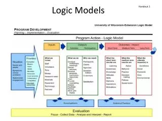
Motivation Explained informally (in English) • Design patterns (DPs) • Reusable solutions to commonly occurring design problems • Represented in Alexandrian form • Synopsis, Context, Forces, Solution, Consequences, Implementation, Examples, Related patterns • Proper use can improve software quality and development productivity • Reduce ambiguity • Automated tool support Clarified with illustrative diagrams Specific code examples Seminar: Recognition of Patterns in Design Models
Existing works 1 • Tool support to the application of DP • Instantiation of patterns • Generating an instance of a design pattern • Widely available in modelling tools • Recognition of patterns • Code level • Recognizing instances of patterns by analyzing the program code • Design level • Recognizing instances of patterns by analyzing the design documents, especially UML diagrams Seminar: Recognition of Patterns in Design Models
e.g. SQL queries e.g. Prolog queries e.g. Prolog clauses e.g. Relational DB e.g. Prolog execution engine e.g. DBMS/SQL server Code Level DP Recognition Tools Architecture of the tools e.g. Java Program Program Code Code Analyzer Pattern Library Program Code intermediate representation Pattern Match Engine Seminar: Recognition of Patterns in Design Models
Code Level DP Recognition Tools • Current state of art • More than a dozen such tools have been reported in the literature; • See (Dong, Zhao and Peng, SERP 2007) for a survey; • Well-known examples: • HEDGEHOG (Blewitt, Bundy and Stark, ASE 2005) • FUJABA (Niere, et al. ICSE 2002) • PINOT (Shi and Olsson, ASE 2006) • Problems • Low level of abstraction • Late in development process • Hard to improve precision and recall rate Seminar: Recognition of Patterns in Design Models
Prolog statements Prolog execution engine Special SW that matches UML diagram to RBML meta-models Design/Model Level DP Recognition Tools UML diagram Software Design Model Architecture Meta-models in RBML Specification of design patterns Model Analyzer Pattern Library Model intermediate representation Pattern Match Engine Seminar: Recognition of Patterns in Design Models
Design/Model Level DP Recognition Tools • Current state of art • (Kim and Lu, ICECCS’06): • Translate RBML and UML into Prolog • (Kim and Shen, SAC’07, SQJ 2008): RBMLCC • Plug-in to IBM Rational Rose • Patterns are specified by meta-models in RBML • Applied to 7 of the 23 GoF patterns • Used class diagram only • Problems • Unclear about precision and recall rate. • Behaviour features of DPs are not considered. Seminar: Recognition of Patterns in Design Models
Our Approach UML diagram: Class diagram + sequence diagram Software Design Model Specification of design patterns in first order logic Based on the formal descriptive semantics of the UML language Model Analyzer Pattern Library Statements in first order predicate logic Model intermediate representation Logic inference engine Pattern Match Engine Seminar: Recognition of Patterns in Design Models
UML Meta-Model LAMBDES: Logic Analyser of Models and Meta-Models Based on Descriptive Semantics of UML Logic statements in SPASS format SPASS: A general purpose first order predicate logic inference engine Implementation 1: LAMBDES-DP UML diagram: Class diagram + sequence diagram Software Design Model Specification of design patterns in first order logic Model Analyzer Pattern Library Model intermediate representation Pattern Match Engine Seminar: Recognition of Patterns in Design Models
UML to SPASS translator Logic statements in SPASS format SPASS Implementation 2 Specification of design patterns in first order logic UML diagram: Class diagram + sequence diagram Software Design Model Model Analyzer Pattern Library Model intermediate representation Pattern Match Engine Seminar: Recognition of Patterns in Design Models
UML to Prolog translator Prolog statements Prolog Interpreter Implementation 3 UML diagram: Class diagram + sequence diagram Specification of design patterns in first order logic Software Design Model Model Analyzer Pattern Library Model intermediate representation Pattern Match Engine Seminar: Recognition of Patterns in Design Models
Formalisation of DPs Two approaches in the literature: • Definition of the structural and behavioural features of design patterns • Using a graphic meta-modelling language • Extension of UML meta-model • Devise new meta-modelling language • Using formal logics • Transformation of “non-standard” designs into instances of patterns • e.g. Lano et al. (1996) Seminar: Recognition of Patterns in Design Models
Specification of DPs as Graphic Meta-Models • Well-known works • Lauder and Kent (1998): • UML meta-model • Le Guennec et al. (UML 2000): • an extension of the UML meta-model and OCL • Eden (2001): • the graphical language LePUS • Mapelsden et al. (CRPIT ’02): • Design Pattern Modeling Language • Kim, France, Ghosh, and Song (COMPSAC 2003): • Role-based metamodelling language RBML Seminar: Recognition of Patterns in Design Models
Problems in Graphic Meta-Modelling Thus, the need of OCL • Expressiveness: • Difficult (if not impossible) to specify negative features • such as to specify no association between two classes • Difficult (if not impossible) to specify variant features • such as to specify object adapter and class adapter patterns in one meta-model • Readability: • Graphic meta-models are hard to understand • Precision: • Meta-modelling languages are usually informally defined • It is non-trivial to define what is an instance of a meta-model Seminar: Recognition of Patterns in Design Models
Formalisation of DPs in Formal Logics • Well-known works • Mikkonen (ICSE’98): • the use of predicate logic to specify structural features • Taibi (2003, 2006): • the use of first order predicate logic to specify structural features and temporal logic to specify behavioural features • Bayley and Zhu (SEFM’07, COMPSAC’08, QSIC’08, JSS 2010): • GEBNF definition of UML abstract syntax • Formal predicate logic induced from GEBNF syntax definition • Specify both structural and behavioural features Seminar: Recognition of Patterns in Design Models
Our Work on Specification of DPs Formal meta-modelling in first order logic (Bayley and Zhu 2007, 2008, 2009, 2010) • Basic ideas: • The abstract syntax of UML diagrams specified in GEBNF (Graphically Extended BNF). • A formal predicate logic (FOL) language systematically derived from the abstract syntax definition • Specifying design patterns in the FOL as predicate on UML diagrams and pattern instantiation is predicate satisfaction. Seminar: Recognition of Patterns in Design Models
GEBNF: Example Non-terminal symbol: the type of entities in the model. ClassDiagram ::= classes : Class+, assocs,inherits, CompAg : Rel* Class ::= name : String , [attrs : Property*], [opers : Operation*] Rel ::= [name : String ], source, end : End End ::= node : Class, [name : String ], [mult : MultiplicityElement] Functionsymbol: function induced from the syntax definition. For example, classes is a function from “ClassDiagram” to the set of “Classes” in the diagram. Terminal symbol: the basic entities that may occur in a model. For example, here ‘String’ represent any string of characters can be used as the name of the relation. Referential occurrence of non-terminal symbol: the model construction contains a reference to an existing element of the type of entities. Here, the end of a relation refers to an existing class in the diagram. Seminar: Recognition of Patterns in Design Models
= Example: Template Method pattern Seminar: Recognition of Patterns in Design Models
Comparison with Other Approaches • Expressiveness: • Both structural feature and behavioural features are specified in the same FOL • Variants of patterns can be specified • All 23 GoF patterns are specified • Readability: • More readable than its rivals • Tool support • Facilitate reasoning, • To formally prove patterns’ properties and relationships • To recognise pattern instances in designs • Facilitate operations and transformations of DPs • E.g. to compose patterns: A Calculus of DP Composition Seminar: Recognition of Patterns in Design Models
Our Work on Semantics of UML Semantics of UML models (Shan and Zhu, 2008, 2009) • Basic Ideas: the formal semantics of UML is defined separately on two aspects: • descriptive semantics: • defines which systems are instances of a model. • e.g. the system consists of two classes A and B, and A is a subclass of B. • functional semantics: • defines the basic modeling concepts, • e.g. If class X is a subclass of Y, then all instances of X are also instances of Y. It describes the system without referring to what is meant by class and subclass. It defines the notion of class and subclass. Seminar: Recognition of Patterns in Design Models
Translation of models into Formal Logic • Signature mapping: rules to derive symbols of FOL from the metamodel • Axiom mapping: rules to derive statements in the FOL from the metamodel that must be true for all valid models • Translation mapping: rules to translate a graphical model into predicates in FOL that it is true if and only if a system is an instance of the model • Hypothesis mapping: rules that selected by the user to be applied in order to characterise the context in which the model is used Seminar: Recognition of Patterns in Design Models
Example: • The following is a subset of the predicates generated from the diagram Seminar: Recognition of Patterns in Design Models
Bridging the Gap • Differences between the FOL for DP spec and the FOL for UML semantics • Syntactic difference • Semantic difference • Predicates in a DP specification are evaluated on UML models • Predicates in the descriptive semantics of UML models are evaluated on software systems • DP specification is translated into the syntax of FOL for descriptive semantics Seminar: Recognition of Patterns in Design Models
Example: • The specification of Template Method can be translated into: Seminar: Recognition of Patterns in Design Models
P is a pattern. Spec(P) is the formal specification of P. The descriptive semantics of model m. System s is an instance of model m. System s satisfies the specification. Recognition of a pattern at design level becomes a logic inference problem. Seminar: Recognition of Patterns in Design Models
The Tool LAMBDES-DP Seminar: Recognition of Patterns in Design Models
Experiments: 1. Use StarUML to produce design instances as UML diagrams and export them as XMI representations. 2. Use LAMBDES to convert these XMI representations to FOL; 3. Use LAMBDES to check these FOL representations for consistency errors, revising them until there are no more errors; 4. For each pattern, use LAMBDES-DP to determine if the model conforms to (i.e. implies the specification of) the pattern. • Three possible outcomes: • Proof Found, meaning definitely yes, • Completion Found, meaning definitely no, and • Time Out, meaning that no proof was found in the maximum time limit that SPASS allows, which is 990 seconds. Seminar: Recognition of Patterns in Design Models
Subjects of the experiments • Patterns: • 23 Patterns in GoF book • Design Instances: Two sets of design instances were produced manually from the diagrams in the GoF book. • Set 1 (Class Only): contains a class diagram for each of the 23 patterns in the book. • Set 2 (Class + Seq): contains class and sequence diagrams for the only 6 patterns in the book that contain both. Seminar: Recognition of Patterns in Design Models
Overview of the Design Instances: ClassOnly Set Seminar: Recognition of Patterns in Design Models
Overview of the Design Instances: Class+Seq Set Seminar: Recognition of Patterns in Design Models
Experiment Results • Why is the false positive error rate so high for class only subjects? • Can we improve the error rate? • Is there a limit to which the error rate can be improved? Seminar: Recognition of Patterns in Design Models
Why is the error rate is so high? • Interdependence between patterns • Inadequate specification of design patterns • Inclusive relationships between patterns • Redundancy in the subject models used in the experiment • a model for testing its conformance to one pattern may coincidently contain an instance of another pattern Seminar: Recognition of Patterns in Design Models
Inclusion Relation on Patterns Definition 1. (Inclusion relation on patterns) A pattern Aincludes pattern B if the logic specification of pattern A implies the logic specification of pattern B. Formally, Spec(A)Spec(B). Theorem 1. For all patterns A and B, if a model contains an instance of pattern A, then the model must also contains an instance of pattern B if A includes B. Seminar: Recognition of Patterns in Design Models
Redundancy in test models Definition 2. (Inclusion relation on models)A model Astructurally includes (or includes for short) model B if B can be obtained by deleting some elements and systematically renaming the elements in B. In such a case, we say that model A is a superset of model B, or B is a subset of model A. Theorem 2. For all models A and B, if model B contains an instance of a DP and B is a subset of model A, then, A also contains an instance of the DP. Seminar: Recognition of Patterns in Design Models
Inclusions between DP Specs and Test Models Seminar: Recognition of Patterns in Design Models
The limit of false positive error rates Definition 3. (Minimal model of design pattern) A model M is a minimal model of a design pattern DP, if it contains an instance of pattern DP and any model obtained by removing an element from M contains no instance of pattern DP. Corollary of Theorem 2. For all sets of models to test the same set of specifications of the design patterns used in the experiment, the error rate of false positives must be greater than or equal to the error rate obtained in the test on the minimal models. Seminar: Recognition of Patterns in Design Models
Results of Testing against Minimal Models The error rate is ≈8%. Seminar: Recognition of Patterns in Design Models
Conclusion: • Recognition of patterns at design level can be accurate with good precision and recall rate; • Behavioural feature is crucial for accurate specification and hence the recognition of patterns, as we have argued in (Bayley and Zhu, COMPSAC 2008); Seminar: Recognition of Patterns in Design Models
Future work • Experiment with industrial real systems • Integration with code level tools • Some tools extract information from code and represent the extracted information in the form of first order logic predicates Seminar: Recognition of Patterns in Design Models
References • I. Bayley and H. Zhu. Formalising design patterns in predicate logic. In Proc. of SEFM’07, pp 25–36. • I. Bayley and H. Zhu. Specifying behavioural features of design patterns in first order logic. Proc. of COMPSAC’08, pp203–210. • L. Shan and H. Zhu. A formal descriptive semantics of UML. Proc. of ICFEM’09, pp375–396. • H. Zhu, I. Bayley, L. Shan and R. Amphlett, Tool Support for Design Pattern Recognition at Model Level, Proc. of COMPSAC'09, July 2009. • L. Shan and H. Zhu, Semantics of Metamodels in UML, Proc. of TASE’09, Aug. 2009 • H. Zhu, L. Shan, I. Bayley and R. Amphlett, A Formal Descriptive Semantics of UML And Its Applications, in UML 2 Semantics and Applications, Kevin Lano (Eds.), John Wiley & Sons, pp95-123, Nov. 2009. • I. Bayley and H. Zhu, Formal Specification of the Variants and Behavioural Features of Design Patterns, Journal of Systems and Software Vol. 83, No. 2, Feb. 2010, pp 209–221 Seminar: Recognition of Patterns in Design Models