Download
1 / 55
560 likes | 746 Views
Measuring Erodibility of Cohesive Soils. By Gregory J. Hanson USDA-ARS Hydraulic Engineering Research Unit. Overview Importance of measuring erodibility. Development of erodibility measurement apparatus Description of Apparatus and method of testing Analysis of results

E N D
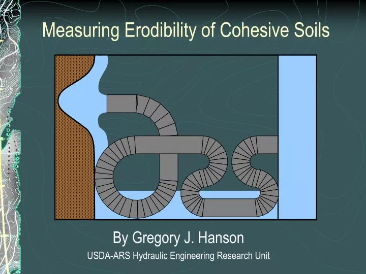
Measuring Erodibility of Cohesive Soils By Gregory J. Hanson USDA-ARS Hydraulic Engineering Research Unit
Overview Importance of measuring erodibility. Development of erodibility measurement apparatus Description of Apparatus and method of testing Analysis of results Things to be aware of in testing and analysis Conclusions
Overview Importance of measuring erodibility. Development of erodibility measurement apparatus Description of Apparatus and method of testing Analysis of results Things to be aware of in testing and analysis Conclusions
Overview Importance of measuring erodibility. Development of erodibility measurement apparatus Description of Apparatus and method of testing Analysis of results Things to be aware of in testing and analysis Conclusions
ESSENTIAL CRITERIA OF AN EROSION TEST • APPLICABLE IN CURRENT EQUATIONS • BASED ON SOUND HYDRAULIC PRINCIPLES • BASED ON KNOWLEDGE OF MATERIALS • REPEATABLE AND CONSISTANT • SIMPLE, QUICK, AND INEXPENSIVE • APPLICABLE TO IN-SITU AND LAB TESTING
Several methods are available for testing of soils. • Wan and Fell (2004) place them in six categories: • Flume tests • Jet erosion tests • Rotating cylinder test • Soil dispersion test • Hole or crack tests • Erosion Function Apparatus
Flume Tests Surface Detachment Headcut Migration • Widening • Discharge dX/dt dY/dt
ESSENTIAL CRITERIA OF AN EROSION TEST • APPLICABLE IN CURRENT EQUATIONS • BASED ON SOUND HYDRAULIC PRINCIPLES • BASED ON KNOWLEDGE OF MATERIALS • REPEATABLE AND CONSISTANT • SIMPLE, QUICK, AND INEXPENSIVE • APPLICABLE TO IN-SITU AND LAB TESTING
Several methods are available for testing of soils. • Wan and Fell (2004) place them in six categories: • Flume tests • Jet erosion tests • Rotating cylinder test • Soil dispersion test • Hole or crack tests • Erosion Function Apparatus
A non-submerged jet test was used as a relative measure of erosion resistance .
ESSENTIAL CRITERIA OF AN EROSION TEST • APPLICABLE IN CURRENT EQUATIONS • BASED ON SOUND HYDRAULIC PRINCIPLES ? • BASED ON KNOWLEDGE OF MATERIALS • REPEATABLE AND CONSISTANT • SIMPLE, QUICK, AND INEXPENSIVE ? • APPLICABLE TO IN-SITU AND LAB TESTING
Ji (ASTM STD D5852-95)
ESSENTIAL CRITERIA OF AN EROSION TEST • APPLICABLE IN CURRENT EQUATIONS • BASED ON SOUND HYDRAULIC PRINCIPLES • BASED ON KNOWLEDGE OF MATERIALS • REPEATABLE AND CONSISTANT ? • SIMPLE, QUICK, AND INEXPENSIVE • APPLICABLE TO IN-SITU AND LAB TESTING
Erodibility Measurement Surface Detachment d dY/dt dY/dt = Er = kd(te – tc)a
ESSENTIAL CRITERIA OF AN EROSION TEST • APPLICABLE IN CURRENT EQUATIONS • BASED ON SOUND HYDRAULIC PRINCIPLES • BASED ON KNOWLEDGE OF MATERIALS • REPEATABLE AND CONSISTANT • SIMPLE, QUICK, AND INEXPENSIVE • APPLICABLE TO IN-SITU AND LAB TESTING
Overview Importance of measuring erodibility. Development of erodibility measurement apparatus Description of Apparatus and method of testing Analysis of results Things to be aware of in testing and analysis Conclusions
Vertical jet apparatus: Pump Head tank Jet Tube Submergence tank Hoses Point gage Pressure gage Valves
Gage point Adjustable head tank Jet tube Hoses Water Source Nozzle Lid Deflector Specimen Submergence tank Laboratory JET Device
Procedure for conducting JET 1) Layout location of pump head tank, jet apparatus, and hoses for convenience and safety of the operator.
Procedure for conducting JET 2) Once the site is located and layout is determined, drive the submergence tank into the soil surface.
Procedure for conducting JET 3) After the tank is set, the jet tube and point gage are attached to the submergence tank.
Procedure for conducting JET • Set the head tank & mast on the submergence tank and set the head tank height.
Procedure for conducting JET 5. Connect hoses from 1) water supply to head tank, 2) head tank to jet tube, and 3) head tank overflow.
Procedure for conducting JET 6. Determine the height of the jet nozzle (orifice) Ji by taking point gage readings at the nozzle and initial soil surface reading at time zero. Also take a zero point gage reading at the deflector plate as a reference point. Enter the point gage readings on the data sheet. 7. Place the deflector plate in front of the jet nozzle and set the point gage against the plate. This closes off the nozzle. Initiate flow to the head tank and jet tube. This process should remove air from the hose between the jet tube and head tank. At the top of the jet tube is also an air release valve to remove air from the jet tube.
Procedure for conducting JET 8. Once the system is filled with water, set the point gage upstream of the jet nozzle at least 10 nozzle diameters to eliminate any flow disturbance from the point gage. The water then proceeds to impact the deflector plate and fill the submergence tank. 9. Once the submergence tank is filled, take an initial head reading by measuring the distance from the top of the head tank to the top of the water surface in the submergence tank or stream channel, whichever is higher. Then move the deflector plate out of the way of the orifice to begin testing. Record the time of test initiation and duration.
Procedure for conducting JET 10.Take point gage readings of the bed at time intervals adjusted to the rate of erosion. Typical time intervals will be 30 sec to 1 min initially and will increase to 10 to 20 minutes depending on the rate of erosion. A set of 10 to 12 readings is recommended with a total test duration of up to 2 hours. The operator may find that it is necessary to feel the tip of the point gage touch the soil surface to avoid pushing the tip into the soil. This is often necessary in soft soils.
Procedure for conducting JET Match the stress range of interest to the stress magnitude of the jet test. The initial stress is set by the controlling the height of the nozzle and the head on the jet, h.
Overview Importance of measuring erodibility. Development of erodibility measurement apparatus Description of Apparatus and method of testing Analysis of results Things to be aware of in testing and analysis Conclusions
Two Step Process: 1. Determine critical tractive stress 2. Determine the erodibility coefficient
er= kd(te-tc) In-situ and Laboratory Measurement of Erodibility