Download

1 / 23
250 likes | 481 Views
Wireless and Mobile Communication Systems. Lecture Slide Part 1 Version 2011-2012 Mohd Nazri Mahmud. Introduction, OBE. This course reviews the topics on optical fibre, wireless & mobile and satellite communication systems.

E N D
Wireless and Mobile Communication Systems Lecture Slide Part 1 Version 2011-2012 Mohd Nazri Mahmud
Introduction, OBE • This course reviews the topics on optical fibre, wireless & mobile and satellite communication systems. • It covers the topics of system components, channels, operations and performance. • Important concepts are introduced and necessary analytical techniques are applied to solve system problems.
Reference books (for wireless and mobile) • Schwartz, M., “ Mobile Wireless Communications”, Cambridge University Press, 2005 • Gary S. Rogers, John Edwards, “An Introduction to Wireless Technology “, Prentice Hall, 2003 • Tse, D.and Viswanath, P.,”Fundamentals of Wireless Communication”, Cambridge University Press, 2005. • Simon Haykin, Micheal Moher, “Modern Wireless Communication”, Pearson Prentice Hall, 2005
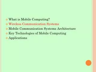
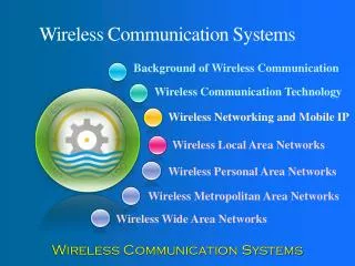
Introduction • What is a wireless communication system? • What is a mobile communication system? • Different types of wireless and mobile systems • Cellular • Wireless LAN • Wireless WAN • Wireless PAN • Wireless Sensor Network • Wireless BAN • Mobile Ad-hoc network (MANET) • Cooperative wireless network • Cognitive Radio Network
Group assignment – facts finding • Divide into 7 groups (3 students per group) • Group 1: Cellular • Group 2: WiFi and WiMAX • Group 3: WPAN and WSN • Group 4: WBAN • Group 5: MANET • Group 6: Cooperative Wireless Network • Group 7: Cognitive Radio Network • Find and read general information regarding these communication systems • Develop a 5 minutes presentation to share your understanding on these systems. Just share what you understand from your reading and avoid complicated analytical contents. Make sure you record all your references • Present in the next class (next week)
Characteristics of Mobile Wireless radio propagation 6 common effects • Propagation loss • Fresnel effect • Fading • Large Scale (Shadow fading) • Small scale (multipath fading) • Flat fading: Rayleigh or Rician • Frequency Selective Fading • Small scale fading due to movements:Doppler effects • Fast or Slow fading • Time-selective fading
Characteristics of Mobile Wireless radio propagation • In free space propagation, the power incident on a receiving antenna is given by the free space received power equation • In wireless environment where obstacles exist, the average power decrease with distance at a rate greater than d2 (usually to the power of 3 or 4) • This is commonly known as the propagation loss
Characteristics of Mobile Wireless radio propagation • The actual power received over a relatively long distance will vary randomly about the average power • A good approximation reveals that the power measured in decibel follows a gaussian or normal distribution centred about its average value with some standard deviation ranging typically from 6 to 10dB. • The power probability distribution is commonly called a log-normal distribution • This is commonly referred to as the shadow fading
Characteristics of Mobile Wireless radio propagation • The actual power received over a much smaller distance also vary considerably due to the destructive/constructive interference of multiple signals that follow multiple paths • This is commonly referred to as multipath fading
Characteristics of Mobile Wireless radio propagation • The three effects can be modelled by the following equation Multipath fading Propagation loss Shadow fading
Characteristics of Mobile Wireless radio propagation • The effect of multipath fading depends of the signal bandwidth • For a relatively large bandwidth, different frequency components of the signal being handled differently over the propagation path leading to signal distortion called frequency selective fading • This is manifested in inter-symbol interference (ISI) due to successive digital symbols overlap into adjacent symbol intervals • For narrower signal bandwidth, non-selective or flat fading occur
Characteristics of Mobile Wireless radio propagation • Terminal mobility with respective to the incoming wave introduces a frequency shift called Doppler shift • Signal fades due to the movement of the terminal
Characteristics of Mobile Wireless radio propagation • Time selective fading occurs when the channel changes its characteristics during the transmission of the signal • The change in the channel characteristics is proportional to the receiver mobility
Propagation loss • The average power measured at the receiver at a distance d from the transmitter is given by • g(d) represents the path loss with the general expression
Propagation loss • There are many models for the path loss • A common two-ray model is most often used
Propagation loss: Two-ray model • The two-ray model is the simplest representation that models the effect on the average received power of multiple rays due to reflection, diffraction and scattering • It treats the case of a single reflected ray • Provides reasonably accurate results in macrocellular environment with relatively high BS antenna and/or L.O.S conditions • Assumes that the signal arrives directly through a L.O.S path and indirectly through perfect relfection from a flat ground surface
Propagation loss: Two-ray model • The reflected signal shows up with a delay relative to the direct path signal and as a consequence, may add constructively (in phase) or destructively (out of phase) • Propagation starts out with an R2 falloff rate and then transitions to a R4 falloff rate at greater ranges. • The "point" where this transition occurs is often called the Fresnel breakpoint. • The nulls are representative of points where direct and reflected signals cancel while the humps show points where signals add • In practice, ground reflections are usually somewhat diffuse (rough mirror instead of polished) and so the sharp nulls get filled in. • In macrocellular communications systems, operating distances are usually large enough so that signal strength can be thought of as falling off at an R4 rate.
Fresnel Effects • Propagation loss due to obstruction in the LOS path • If there are obstacles near the LOS path between the transmitter and the receiver, the radio waves reflecting off these objects may arrive out of phase with the direct LOS signal • The power of the received signal might be reduced • There is a zone called Fresnel zone that must be clear of any obstacle • There are multiple Fresnel zones; 1st , 2nd, 3rd and so on • Signal within one set of a Fresnel zone have similar strength • The Fresnel zones are half-wavelength apart from one another
Fresnel Effects • The radius of the 1st Fresnel zone depends on the frequency and the antenna height • It is often useful to know the maximum radius of the first Fresnel zone in which the primary signal energy resides • The first Fresnel zone must be kept largely free from obstructions • General equation for calculating the Fresnel zone radius at any point P Fn = The nth Fresnel zone radius (in metres) d1 = The distance of P from one end (in metres) d2 = The distance of P from the other end (in metres) Λ = the wavelength of the transmitted signal (in metres)
Propagation loss: Other models • Hata model or aka Okumura-Hata model • A journal paper on Hata model is provided online (in my staff webpage) • Please print the paper and bring to our next class • Group reading in class: Read and understand Hata’s paper within your group • Base your understanding from group discussions only (without referring to your lecturer). This is to encourage group members to assist one another in learning • A quiz will be held in the next class