Download
1 / 50
520 likes | 780 Views
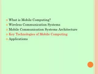
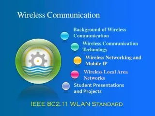
Wireless Communication Systems. Background of Wireless Communication. Wireless Communication Technology. Wireless Networking and Mobile IP. Wireless Local Area Networks. Wireless Personal Area Networks. Wireless Metropolitan Area Networks. Wireless Wide Area Networks. Physical Layer.

E N D
Wireless Communication Systems Background of Wireless Communication Wireless Communication Technology Wireless Networking and Mobile IP Wireless Local Area Networks Wireless Personal Area Networks Wireless Metropolitan Area Networks Wireless Wide Area Networks Physical Layer
Overview • Physical Properties of Wireless • Frequency & Public Use Bands • Free-space Path-loss • Path-loss Exponents • Multi-path Propagation • Multi-Path Effect • Digital Modulation • Examples of Digital Modulation • Multi-transmitter Interference • Symbol Rate & Bandwidth • Thermal Noise • Multi-transmitter Interference Problem • Medium Access Control • CSMA, CSMA-CD, CSMA/CA • Random Contention Access • Distributed Coordination Function (DCF) • 802.11 Contention Window • 802.11 Adaptive Contention Window • DCF Protocol Issues • Virtual Carrier Sense • Physical Carrier Sense Mechanisms • Exposed Terminal Problem • Double Exposed Terminal Problem • Point Coordination Function (PCF)
Physical Properties of Wireless Makes wireless network different from wired networks Should be taken into account by all layers
Wireless = Waves Electromagnetic radiation Emitted by sinusoidal current running through a wire (transmitting antenna) Creates propagating sinusoidal magnetic and electric fields according to Maxwell’s equations: Fields induce current in receiving antenna
Wave Propagation Example electric field propagation direction magnetic field
Frequency & Public Use Bands Propagating sinusoidal wave with some frequency/wavelength C (speed of light) = 3x10⁸ m/s
Free-space Path-loss Power of wireless transmission reduces with square of distance (due to surface area increase of sphere) Reduction also depends on wavelength Long wave length (low frequency) has less loss Short wave length (high frequency) has more loss
Other Path-loss Exponents Path-Loss Exponent depends on environment: Free space 2 Urban area cellular 2.7 to 3.5 Shadowed urban cell 3 to 5 In building LOS 1.6 to 1.8 Obstructed in building 4 to 6 Obstructed in factories 2 to 3
Multi-path Propagation Electromagnetic waves bounce off of conductive (metal) objects Reflected waves received along with direct wave
Multi-Path Effect Multi-path components are delayed depending on path length (delay spread) Phase shift causes frequency dependent constructive / destructive interference Amplitude Amplitude Time Frequency
Digital Modulation Modulation allows the wave to carry information by adjusting its properties in a time varying way Amplitude Frequency Phase Digital modulation using discrete “steps” so that information can be recovered despite noise/interference
Examples of Digital Modulation BPSK QPSK ODFM • Digital modulation Practical examples • BFSK - Mote Sensor Networks • QPSK - 2 Mbps 802.11 & CMDA(IS-95)
Multi-transmitter Interference Similar to multi-path Two transmitting stations will constructively/destructively interfere with each other at the receiver Receiver will “hear” the sum of the two signals, which usually means garbage
Symbol Rate & Bandwidth Modulation allows transmission of one of several possible symbols Data stream is encoded by transmitting several symbols in succession Symbol rate ≈ bandwidth Throughput (bits/sec) Spectrum usage (Hz) Inter-symbol interference (ISI) occurs unless delay spread << symbol time
Thermal Noise Ever-present thermal noise in wireless medium Sums with any wireless transmission Potentially causes errors in reception (digital) or degradation of quality (analog) Effectively limits transmission range when transmitting signal strength falls below noise floor
Noise Limits Transmitting Distance Short range transmission (low path loss) Signal to Noise Ratio (SNR) + = High Long range transmission (high path loss) = + Low
Physical Channel Properties Review Wireless signal strength Transmit power Loss over distance (falls off by d2) Shadowing (e.g. absorption by walls) Multi-path (e.g. bouncing off of metal objects) Noise Thermal noise floor Environmental noise (e.g. microwave ovens) Channel quality Related to signal to noise ratio
Multi-transmitter Interference Problem Similar to multi-path or noise Two transmitting stations will constructively/destructively interfere with each other at the receiver Receiver will “hear” the sum of the two signals (which usually means garbage)
Medium Access Methods The 802.11 standard ensures that all stations, both radio-based network interface cards (NICs) and access points, implement access methods for sharing the air medium. When installing wireless LANs (WLAN), most people don't give much thought to these mechanisms. A solid understanding of 802.11's medium access methods, will enable us to deal more effectively with issues such as radio frequency interference, denial of services attacks and throughput issues.
Medium Access Control (MAC) Protocol required to coordinate access i.e. transmitters must take turns Similar to talking in a crowded room Also similar to hub based Ethernet
Carrier Sense Multiple Access (CSMA) Procedure Listen to medium and wait until it is free (no one else is talking) Wait a random back off time then start talking Advantages Fairly simple to implement Functional scheme that works Disadvantages Can not recover from a collision (inefficient waste of medium time)
Carrier Sense Multiple Accesswith Collision Detection (CSMA-CD) Procedure Listen to medium and wait until it is free Then start talking, but listen to see if someone else starts talking too If a collision occurs, stop and then start talking after a random back off time This scheme is used for hub based Ethernet Advantages More efficient than basic CSMA Disadvantages Requires ability to detect collisions
Collision Detection Problem Transmit signal is MUCH stronger than received signal Due to high path loss in the wireless environment Impossible to “listen” while transmitting because you will drown out anything you hear Also transmitter may not even have much of a signal to detect due to geometry
Carrier Sense Multiple Accesswith Collision Avoidance (CSMA-CA) Procedure Similar to CSMA but instead of sending packets control frames are exchanged RTS = request to send CTS = clear to send DATA = actual packet ACK = acknowledgement
Carrier Sense Multiple Accesswith Collision Avoidance (CSMA-CA) Advantages Small control frames lessen the cost of collisions (when data is large) RTS + CTS provide “virtual” carrier sense protects against hidden terminal collisions (where A can’t hear B) A B
Carrier Sense Multiple Accesswith Collision Avoidance (CSMA-CA) Disadvantages Not as efficient as CSMA-CD Doesn’t solve all the problems of MAC in wireless networks
Random Contention Access Slotted contention period Used by all carrier sense variants Provides random access to the channel Operation Each node selects a random back off number Waits that number of slots monitoring the channel If channel stays idle and reaches zero then transmit If channel becomes active wait until transmission is over then start counting again
Distributed Coordination Function (DCF) The 802.11 standard makes it mandatory that all stations implement the DCF, a form of carrier sense multiple access with collision avoidance (CSMA/CA). CSMA is a contention-based protocol making certain that all stations first sense the medium before transmitting. The main goal is to avoid having stations transmit at the same time, which results in collisions and corresponding retransmissions.
Distributed Coordination Function (DCF) If a station wanting to send a frame senses energy above a specific threshold on the medium (which could mean the transmission of another station), the station wanting access will wait until the medium is idle before transmitting the frame. The collision avoidance aspect of the protocol pertains to the use of acknowledgements that a receiving station send to the sending station to verify error-free reception. Think of this process of accessing the medium as a meeting where everyone is polite and each person only speaks when no one else is talking. In addition, everyone who understands what the person is saying nods their head in agreement.
Distributed Coordination Function (DCF) The DCF protocol is somewhat more complex than this, though. For example, an 802.11 station utilizes information it gains from other frames that stations are sending over the wireless network. In the control field of each frame, there is a duration field that a sending station places a value in, to indicate how long the station will require the medium. As part of making a decision on whether to transmit a frame, a station must see that the time associated with the duration value of the last frame sent has expired, as well as sense that no physical transmission is taking place. The duration field enables stations to reserve the medium for subsequent frames of some specific 802.11-defined frame exchanges (e.g. RTS/CTS)
802.11 DCF Example with Backoff B1 = 25 B1 = 5 wait data data wait B2 = 10 B2 = 20 B2 = 15 B1 and B2 are backoff intervals at nodes 1 and 2 cw = 31
802.11 Contention Window Random number selected from [0,cw] Small value for cw Less wasted idle slots time Large number of collisions with multiple senders (two or more stations reach zero at once) Optimal cw for known number of contenders & know packet size Tricky to implement because number of contenders is difficult to estimate and can be VERY dynamic
802.11 Adaptive Contention Window 802.11 adaptively sets cw Starts with cw = 31 If no CTS or ACK then increase to 2*cw+1 (63, 127, 255) Reset to 31 on successful transmission 802.11 adaptive scheme is unfair Under contention, unlucky nodes will use larger cw than lucky nodes (due to straight reset after a success) Lucky nodes may be able to transmit several packets while unlucky nodes are counting down for access Fair schemes should use same cw for all contending nodes (better for high congestion too)
802.11 DCF (CSMA-CA) Full exchange with “virtual” carrier sense (called the Network Allocation Vector) A B Sender Receiver RTS DATA Sender CTS ACK Receiver NAV (RTS) A NAV (CTS) B
802.11 DCF (CSMA-CA) Because of its nature, DCF supports the transmission of asynchronous signals. A distinguishing factor of asynchronous signaling is that there are no timing requirements between data carrying frames. For example, the DCF protocol doesn't make any attempt to deliver a series of data frames within any timeframe or at any instant in time. As a result, there is a random amount of delay between each data frame transmission. This form of synchronization is effective for network applications, such as e-mail, Web browsing and VPN access to corporate applications.
DCF Protocol Issues The DCF protocol is the heart of many WLAN troubles. RF Interference is probably the biggest problem. If a source of RF interference (e.g., cordless phone or other WLAN) is present, the DCF can block stations from transmitting for as long as the interfering signal is present. The stations sense enough energy on the medium and wait patiently, in most cases for just a few seconds or minutes. This causes the throughput of the network to drop significantly. That's why you should perform an RF site survey in the facility before installing a WLAN.
DCF Protocol Issues Similar to the impact of typical RF interference, someone could implement a denial of service attack, which is a deliberate action to instill RF interference at a level high enough to block a majority of the stations from transmitting. Again, all of the stations will not transmit because they respectfully follow the DCF protocol.
DCF Protocol Issues Similar to the impact of typical RF interference, someone could implement a denial of service attack, which is a deliberate action to instill RF interference at a level high enough to block a majority of the stations from transmitting. Again, all of the stations will not transmit because they respectfully follow the DCF protocol. Instead of lasting for only a few seconds, a denial of service attack could be planned in a way to corrupt the network for hours or days until the jamming source is found. This type of attack will generally cause the network to be useless (i.e., throughput equal to zero). In order to reduce this impact, maximize the use of directional antennas to minimize the reception of RF signals from outside the facility where someone could attack them with a high-powered jamming device
Virtual Carrier Sense Provided by RTS & CTS Designed to protect against hidden terminal collisions (when C can’t receive from A and might start transmitting) However this is unnecessary most of the time due to physical carrier sense RTS CTS B A C
Physical Carrier Sense Mechanisms Energy detection threshold Monitors channel during “idle” times between packets to measure the noise floor Energy levels above the noise floor by a threshold trigger carrier sense DSSS correlation threshold Monitors the channel for Direct Sequence Spread Spectrum (DSSS) coded signal Triggers carrier sense if the correlation peak is above a threshold More sensitive than energy detection (but only works for 802.11 transmissions) High BER disrupts transmission but not detection
Physical Carrier Sense Range Carrier can be sensed at lower levels than packets can be received Results in larger carrier sense range than transmission range Long carrier sense range helps protect from interference Receive Range Carrier Sense Range
Hidden Terminal Revisited Virtual carrier sense no longer needed in this situation RTS CTS B A C Physical Carrier Sense
RTS CTS Still Useful Sometimes Obstructed hidden terminal situation Fast collision resolution for long data packets A B
Exposed Terminal Problem Hidden terminal is not the only challenge for a distributed wireless MAC protocol A blocks B, and C doesn’t know what is happening (B is exposed) D B C A
Double Exposure Problem If A and C are out of phase, there is NO time D can transmit without causing a collision B A C D
Point Coordination Function (PCF) As an optional access method, the 802.11 standard defines the PCF, which enables the transmission of time-sensitive information. With PCF, a point coordinator within the access point controls which stations can transmit during any give period of time. Within a time period called the contention free period, the point coordinator will step through all stations operating in PCF mode and poll them one at a time. For example, the point coordinator may first poll station A, and during a specific period of time station A can transmit data frames (and no other station can send anything). The point coordinator will then poll the next station and continue down the polling list, while letting each station to have a chance to send data.
Point Coordination Function (PCF) Thus, PCF is a contention-free protocol and enables stations to transmit data frames synchronously, with regular time delays between data frame transmissions. This makes it possible to more effectively support information flows, such as video and control mechanisms, having stiffer synchronization requirements. Timing mechanisms within the 802.11 protocol ensure that stations on the WLAN alternate between the use of DCF and PCF. As a result, the WLAN can support both asynchronous and synchronous information flows. For a period of time, stations will access channel by using CSMA. For the following time period, the stations will wait for a poll from the point coordinator before sending data frames.
Point Coordination Function (PCF) The big name vendors, such as Cisco, Proxim, and Symbol, don't include PCF mode in their devices as a standard. Some chipsets have PCF functionality embedded somewhere in the firmware, but access point vendors seem to be reluctant to activate it, even though PCF has been part of the 802.11 standard since its inception in 1997. The problem is that the 802.11 standard is fairly vague in defining portions of the PCF protocol. As a result, you need to use the same vendor for the access points and radio cards to make it work properly. The Wi-Fi Alliance does not include PCF functionality in their interoperability standard.
Q&A • ?
Assignment #1 Explain the terms highlighted in GREENcolor throughout this lecture slide Send your assignments in Word Document Format to adeel@uettaxila.edu.pk or adeel.akram@gmail.com Last date of submission of assignment is 24th March 2009.