Download
1 / 68
680 likes | 694 Views
Chapter 27 Magnetism. 27-4 Force on an Electric Charge Moving in a Magnetic Field. Problem solving: Magnetic fields – things to remember: The magnetic force is perpendicular to the magnetic field direction. The right-hand rule is useful for determining directions.

E N D
27-4 Force on an Electric Charge Moving in a Magnetic Field Problem solving: Magnetic fields – things to remember: • The magnetic force is perpendicular to the magnetic field direction. • The right-hand rule is useful for determining directions. • Equations in this chapter give magnitudes only. The right-hand rule gives the direction.
27-4 Force on an Electric Charge Moving in a Magnetic Field Conceptual Example 27-9: A helical path. What is the path of a charged particle in a uniform magnetic field if its velocity is not perpendicular to the magnetic field?
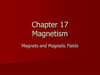
27-4 Force on an Electric Charge Moving in a Magnetic Field The aurora borealis (northern lights) is caused by charged particles from the solar wind spiraling along the Earth’s magnetic field, and colliding with air molecules.
27-4 Force on an Electric Charge Moving in a Magnetic Field Conceptual Example 27-10: Velocity selector, or filter: crossed E and B fields. Some electronic devices and experiments need a beam of charged particles all moving at nearly the same velocity. This can be achieved using both a uniform electric field and a uniform magnetic field, arranged so they are at right angles to each other. Particles of charge q pass through slit S1 and enter the region where B points into the page and E points down from the positive plate toward the negative plate. If the particles enter with different velocities, show how this device “selects” a particular velocity, and determine what this velocity is.
E B = ? v electrons ConcepTest 27.5 Velocity Selector In what direction would a B field have to point for a beam of electrons moving to the right to go undeflected through a region where there is a uniform electric field pointing vertically upward? 1) up (parallel to E ) 2) down (antiparallel to E ) 3) into the page 4) out of the page 5) impossible to accomplish
E B = ? v electrons ConcepTest 27.5 Velocity Selector In what direction would a B field have to point for a beam of electrons moving to the right to go undeflected through a region where there is a uniform electric field pointing vertically upward? 1) up (parallel to E ) 2) down (antiparallel to E ) 3) into the page 4) out of the page 5) impossible to accomplish Without a B field, the electrons feel an electric force downward. In order to compensate, the magnetic force has to point upward. Using the right-hand rule and the fact that the electrons are negatively charged leads to a B field pointing out of the page.
27-5 Torque on a Current Loop; Magnetic Dipole Moment The forces on opposite sides of a current loop will be equal and opposite (if the field is uniform and the loop is symmetric), but there may be a torque. The magnitude of the torque is given by
27-5 Torque on a Current Loop; Magnetic Dipole Moment The quantity NIA is called the magnetic dipole moment, μ: The potential energy of the loop depends on its orientation in the field:
27-5 Torque on a Current Loop; Magnetic Dipole Moment Example 27-11: Torque on a coil. A circular coil of wire has a diameter of 20.0 cm and contains 10 loops. The current in each loop is 3.00 A, and the coil is placed in a 2.00-T external magnetic field. Determine the maximum and minimum torque exerted on the coil by the field.
27-5 Torque on a Current Loop; Magnetic Dipole Moment Example 27-12: Magnetic moment of a hydrogen atom. Determine the magnetic dipole moment of the electron orbiting the proton of a hydrogen atom at a given instant, assuming (in the Bohr model) it is in its ground state with a circular orbit of radius r = 0.529 x 10⁻¹⁰ m. [This is a very rough picture of atomic structure, but nonetheless gives an accurate result.]
N S S N ConcepTest 27.7b Magnetic Force on a Loop II 1) move up 2) move down 3) rotate clockwise 4) rotate counterclockwise 5) both rotate and move If there is a current in the loop in the direction shown, the loop will: B field out of North B field into South
N S ConcepTest 27.7b Magnetic Force on a Loop II 1) move up 2) move down 3) rotate clockwise 4) rotate counterclockwise 5) both rotate and move If there is a current in the loop in the direction shown, the loop will: F Look at the north pole: here the magnetic field points to the rightand the current points out of the page. The right-hand rule says that the force must pointup. At the south pole, the same logic leads to a downward force. Thus the loop rotates clockwise. F
27-6 Applications: Motors, Loudspeakers, Galvanometers An electric motor uses the torque on a current loop in a magnetic field to turn magnetic energy into kinetic energy.
27-6 Applications: Motors, Loudspeakers, Galvanometers Loudspeakers use the principle that a magnet exerts a force on a current-carrying wire to convert electrical signals into mechanical vibrations, producing sound.
27-6 Applications: Motors, Loudspeakers, Galvanometers A galvanometer takes advantage of the torque on a current loop to measure current; the spring constant is calibrated so the scale reads in amperes.
27-8 The Hall Effect When a current-carrying wire is placed in a magnetic field, there is a sideways force on the electrons in the wire. This tends to push them to one side and results in a potential difference from one side of the wire to the other; this is called the Hall effect. The emf differs in sign depending on the sign of the charge carriers; this is how it was first determined that the charge carriers in ordinary conductors are negatively charged.
27-8 The Hall Effect Example 27-13: Drift velocity using the Hall effect. A long copper strip 1.8 cm wide and 1.0 mm thick is placed in a 1.2-T magnetic field. When a steady current of 15 A passes through it, the Hall emf is measured to be 1.02 μV. Determine the drift velocity of the electrons and the density of free (conducting) electrons (number per unit volume) in the copper.
27-9 Mass Spectrometer A mass spectrometer measures the masses of atoms. If a charged particle is moving through perpendicular electric and magnetic fields, there is a particular speed at which it will not be deflected, which then allows the measurement of its mass:
27-9 Mass Spectrometer All the atoms reaching the second magnetic field will have the same speed; their radius of curvature will depend on their mass.
27-9 Mass Spectrometer Example 27-14: Mass spectrometry. Carbon atoms of atomic mass 12.0 u are found to be mixed with another, unknown, element. In a mass spectrometer with fixed B′, the carbon traverses a path of radius 22.4 cm and the unknown’s path has a 26.2-cm radius. What is the unknown element? Assume the ions of both elements have the same charge.
Summary of Chapter 27 • Magnets have north and south poles. • Like poles repel, unlike attract. • Unit of magnetic field: tesla. • Electric currents produce magnetic fields. • A magnetic field exerts a force on an electric current:
Summary of Chapter 27 • A magnetic field exerts a force on a moving charge: • Torque on a current loop: • Magnetic dipole moment:
Units of Chapter 28 • Magnetic Field Due to a Straight Wire • Force between Two Parallel Wires • Definitions of the Ampere and the Coulomb • Ampère’s Law • Magnetic Field of a Solenoid and a Toroid • Biot-Savart Law • Magnetic Materials – Ferromagnetism • Electromagnets and Solenoids – Applications
Units of Chapter 28 • Magnetic Fields in Magnetic Materials; Hysteresis • Paramagnetism and Diamagnetism
28-1 Magnetic Field Due to a Straight Wire The magnetic field due to a straight wire is inversely proportional to the distance from the wire: The constant μ0 is called the permeability of free space, and has the value μ0 = 4π x 10-7 T·m/A.
28-1 Magnetic Field Due to a Straight Wire Example 28-1: Calculation of B near a wire. An electric wire in the wall of a building carries a dc current of 25 A vertically upward. What is the magnetic field due to this current at a point P 10 cm due north of the wire?
28-1 Magnetic Field Due to a Straight Wire Example 28-2: Magnetic field midway between two currents. Two parallel straight wires 10.0 cm apart carry currents in opposite directions. Current I1 = 5.0 A is out of the page, and I2 = 7.0 A is into the page. Determine the magnitude and direction of the magnetic field halfway between the two wires.
28-1 Magnetic Field Due to a Straight Wire Conceptual Example 28-3: Magnetic field due to four wires. This figure shows four long parallel wires which carry equal currents into or out of the page. In which configuration, (a) or (b), is the magnetic field greater at the center of the square?
1 P 4 2 3 ConcepTest 28.1 Magnetic Field of a Wire 1) direction 1 2) direction 2 3) direction 3 4) direction 4 5) the B field is zero If the currents in these wires have the same magnitude but opposite directions, what is the direction of the magnetic field at point P?
ConcepTest 28.1 Magnetic Field of a Wire 1) direction 1 2) direction 2 3) direction 3 4) direction 4 5) the B field is zero If the currents in these wires have the same magnitude but opposite directions, what is the direction of the magnetic field at point P? 1 P Using the right-hand rule, we can sketch the B fields due to the two currents. Adding them up as vectors gives a total magnetic field pointing downward. 4 2 3
ConcepTest 28.2 Field and Force 1) toward each other 2) away from each other 3) there is no force Two straight wires run parallel to each other, each carrying a current in the direction shown below. The two wires experience a force in which direction?
ConcepTest 28.2 Field and Force 1) toward each other 2) away from each other 3) there is no force Two straight wires run parallel to each other, each carrying a current in the direction shown below. The two wires experience a force in which direction? The current in each wire produces a magnetic field that is felt by the current of the other wire. Using the right-hand rule, we find that each wire experiences a force toward the other wire (i.e., an attractive force) when the currents are parallel (as shown). Follow-up: What happens when one of the currents is turned off?
28-2 Force between Two Parallel Wires The magnetic field produced at the position of wire 2 due to the current in wire 1 is The force this field exerts on a length l2 of wire 2 is
28-2 Force between Two Parallel Wires Parallel currents attract; antiparallel currents repel.
28-2 Force between Two Parallel Wires Example 28-4. Force between two current-carrying wires. The two wires of a 2.0-m-long appliance cord are 3.0 mm apart and carry a current of 8.0 A dc. Calculate the force one wire exerts on the other.
28-2 Force between Two Parallel Wires Example 28-5: Suspending a wire with a current. A horizontal wire carries a current I1 = 80 A dc. A second parallel wire 20 cm below it must carry how much current I2 so that it doesn’t fall due to gravity? The lower wire has a mass of 0.12 g per meter of length.
28-3 Definitions of the Ampere and the Coulomb The ampere is officially defined in terms of the force between two current-carrying wires: One ampere is defined as that current flowing in each of two long parallel wires 1 m apart, which results in a force of exactly 2 x 10⁻⁷ N per meter of length of each wire. The coulomb is then defined as exactly one ampere-second.
28-4 Ampère’s Law Ampère’s law relates the magnetic field around a closed loop to the total current flowing through the loop: This integral is taken around the edge of the closed loop.
28-4 Ampère’s Law Using Ampère’s law to find the field around a long straight wire: Use a circular path with the wire at the center; then B is tangent to dl at every point. The integral then gives so B = μ0I/2πr, as before.
28-4 Ampère’s Law Example 28-6: Field inside and outside a wire. A long straight cylindrical wire conductor of radius R carries a current I of uniform current density in the conductor. Determine the magnetic field due to this current at (a) points outside the conductor (r > R) and (b) points inside the conductor (r < R). Assume that r, the radial distance from the axis, is much less than the length of the wire. (c) If R = 2.0 mm and I = 60 A, what is B at r = 1.0 mm, r = 2.0 mm, and r = 3.0 mm?
28-4 Ampère’s Law Conceptual Example 28-7: Coaxial cable. A coaxial cable is a single wire surrounded by a cylindrical metallic braid. The two conductors are separated by an insulator. The central wire carries current to the other end of the cable, and the outer braid carries the return current and is usually considered ground. Describe the magnetic field (a) in the space between the conductors, and (b) outside the cable.
28-4 Ampère’s Law Example 28-8: A nice use for Ampère’s law. Use Ampère’s law to show that in any region of space where there are no currents the magnetic field cannot be both unidirectional and nonuniform as shown in the figure.
28-4 Ampère’s Law Solving problems using Ampère’s law: • Ampère’s law is only useful for solving problems when there is a great deal of symmetry. Identify the symmetry. • Choose an integration path that reflects the symmetry (typically, the path is along lines where the field is constant and perpendicular to the field where it is changing). • Use the symmetry to determine the direction of the field. • Determine the enclosed current.
28-5 Magnetic Field of a Solenoid and a Toroid A solenoid is a coil of wire containing many loops. To find the field inside, we use Ampère’s law along the path indicated in the figure.
28-5 Magnetic Field of a Solenoid and a Toroid The field is zero outside the solenoid, and the path integral is zero along the vertical lines, so the field is (n is the number of loops per unit length)
28-5 Magnetic Field of a Solenoid and a Toroid Example 28-9: Field inside a solenoid. A thin 10-cm-long solenoid used for fast electromechanical switching has a total of 400 turns of wire and carries a current of 2.0 A. Calculate the field inside near the center.
28-5 Magnetic Field of a Solenoid and a Toroid Example 28-10: Toroid. Use Ampère’s law to determine the magnetic field (a) inside and (b) outside a toroid, which is like a solenoid bent into the shape of a circle as shown.