Download
1 / 36
430 likes | 991 Views
Introduction to pressure measurement. Pressure measurement is important because of the following reasons:. Pressure is an important quantity that describes a system. • Pressure is invariably an important process parameter. • Pressure difference is used many a time as a means of measuring the

E N D
Pressure measurement is important because of the following reasons: Pressure is an important quantity that describes a system. • Pressure is invariably an important process parameter. • Pressure difference is used many a time as a means of measuring the flow rate of a fluid. • Pressure level spans some 18 orders of magnitude from the lowest to the highest pressures encountered in practice.
The pressure measuring devices and the corresponding ranges are shown in The table below (حفظ)
Pressure Measurement Divided into three categories: 1. Absolute pressure – pressure at a point in a fluid relative to a vacuum (absolute zero of pressure) 2. Gauge Pressure – pressure relative to local atmospheric pressure. 3. Differential Pressure – difference between two unknown pressures, neither of which is atmospheric pressure.
Forms of pressure Differential pressure Absolute pressure Gauge pressure
Relationship between absolute and gauge pressures Pabs=Pgauge+Patm
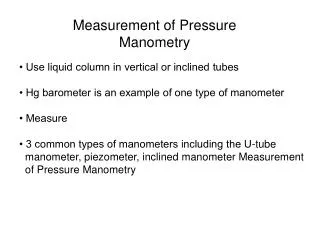
Manometers Column of liquid supported produced pressure P = rh, where is the density of the liquid and h the height of the column. Thus for case a)
Sensors using elastic properties Three types of device: 1. Bourdon Tubes – basis of many mechanical gauges. 2. Bellows – low cost barometers. 3. Diaphragms or Membranes – most commonly used structures for pressure sensing
Bellows a) Single Bellows Gauge (Gauge Pressure) b) Double Bellows Gauge (Differential Pressure)
Capacitive pressure sensors - capacitor – usually differential -Deformation element = pre-strained metallic membrane – serves as grounded electrode -Range: Δp = 1 mbar – 10 bar, total p up to 400 bar
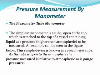
U – Tube manometer The simplest of the gages that is used for measuring pressure is a U – tube manometer shown in the figure below. The U tube needs to be vertically oriented and the acceleration due to gravity is assumed to be known. The height ‘h’ is the measured quantity.
The pressure to be measured is that of a system that involves a fluid (liquid or a gas) different from the manometer liquid. Let the density of the fluid whose pressure being measured be ρf and that of the manometer liquid be ρf. Equilibrium of the manometer liquid requires that there be the same force in the two limbs across the plane AA. We then have This may be rearranged to read
Even though mercury is a common liquid used in manometers, other liquids are also used. A second common liquid is water. When measuring pressures close to the atmospheric pressure in gases, the fluid density may be quite negligible in comparison with the manometer liquid density. One may then use the approximate expression The manometer liquid is chosen based on its density with respect to the density of the fluid whose pressure is being measured and also the pressure difference that needs to be measured. Indeed small pressure differences are measured using water or organic liquids as the manometer liquid such that the height h measured is sufficiently large as to be estimated with sufficient precision.
Well type manometer Sometimes a well type manometer is used. Schematic of a well type manometer is shown in the figure below.
The dashed line indicates the datum with reference to which the manometer height is measured. The advantage of the well type design is that relatively large pressure differences may be measured with enough manometer liquid being available for doing so! We assume that the manometer liquid is incompressible and hence the following holds: * This expression simply states that there is no change in the volume of the fluid and hence the mass. Here ‘A’ is the well cross section area given by while ‘a’ is the tube cross section area given by
Equation * is recast for this case as ** Using Equation * in Equation **, after some rearrangement we get If the area ratio is very small compared to unity, we may use the approximate formula that is identical with Equation
Well type manometer with inclined tube In case the measured pressure difference is small one may use an inclined well type manometer shown in the figure below
The manometer height is now given by The Equation Can be replaced by It is clear that the inclination of the tube amplifies the measured quantity and hence improves the precision of the measurement.
Bourdon gage Bourdon gages are available to cover a large range of pressures. Bourdon gages are purely mechanical devices utilising the mechanical deformation of a flattened but bent tube that winds or unwinds depending on the pressure difference between the inside and the outside. The motion is against a spring torque such that a needle attached to the shaft indicates directly the pressure difference. The working principle of the bourdon gage is explained with reference to the figure below .
- The Bourdon tube is a metal tube of elliptic cross section having a bent shape • as shown above • The inside of the tube is exposed to the pressure to be measured. • The outside of the Bourdon tube is exposed to a second pressure, usually the atmospheric. • The Bourdon tube is held fixed at one end (the end connected to the pressure source) and the other end is connected by linkages to a spring restrained shaft. • A pointer is mounted on the shaft, as indicated in the figure. • The needle moves over a circular scale that indicates the pressure. • The position of the needle is determined by a balance between the Bourdon tube developed torque acting on the shaft and the torque due to the shaft mounted spring that opposes its movement. • The external appearance of a Bourdon gage is as shown in the figure • . Bourdon gages are available for measuring pressures higher/lower than the atmospheric pressure. • The pressure indicated is referred to as the gage pressure if it is with respect to the atmospheric pressure outside the Bourdon tube.
Example of Bourdon tube application : dead weight tester A Bourdon pressure gage may be calibrated by the use of a dead weight tester, a schematic of which is shown in Figure
- The dead weight tester consists of an arrangement by which a piston may be • allowed to float over a liquid (usually oil) under internal pressure and a force in • the opposite direction imposed on the piston by weights placed as indicated in • the figure. • The oil pressure is changed by the pumping piston. • The pressure is calculated as the weight placed on the piston divided by the cross section area of the piston (the piston is to be oriented with its axis vertical). - The gage under test experiences the same pressure by being connected to a side tube communicating with the oil. • A dead weight tester is a precision device and is available from many manufacturers.
Pressure transducers 1. Pressure tube with bonded strain gage 2. Diaphragm/Bellows type transducer 3. Capacitance pressure transducer The common feature of all these transducers is that the pressure to be measured introduces a strain or movement in a mechanical element that is measured by different techniques. The strain is measured by a) strain gage b) linear voltage displacement transducer (LVDT) c) the change in capacitance.
Pressure tube with bonded strain gage The principle of a pressure tube with bonded strain gage may be understood by referring to the figure below.
- The pressure to be measured is communicated to the inside of a tube of suitable wall thickness one end of which is closed with a thick plate. - Because the end plate is very thick it undergoes hardly any strain. The tube, however, experiences a hoop strain due to internal pressure (indicated by the blue arrows). A strain gage mounted on the tube wall experiences the hoop strain. The way the strain gage works is dealt with below.
Diaphragm/Bellows type transducer: Pressure signal is converted to a displacement in the case of diaphragm/bellows type pressure gage. The diaphragm or bellows acts as a spring element that undergoes a displacement under the action of the pressure. Schematic of diaphragm and bellows elements are shown respectively in the figures below (a) and (b).
In the above figure a Linear Variable Differential Transformer (LVDT) is used as a displacement transducer. a strain gage for measuring the strain in the diaphragm by fixing it at a suitable position on the diaphragm .
- The Figure above shows the schematic of a capacitance type pressure transducer. -The gap between the stretched diaphragm and the anvil (remains fixed because of its mass) varies with applied pressure due to the small displacement of the diaphragm. This changes the capacitance of the gap. -The theoretical basis for this is derived below.