1 / 49

By: Shahir A. Safi, PE Kansas City District Corps of Engineers

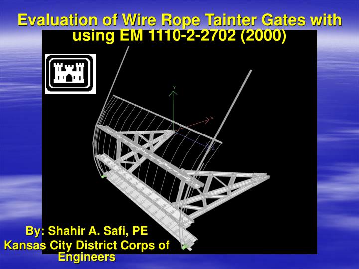
Evaluation of Wire Rope Tainter Gates with using EM 1110-2-2702 (2000). By: Shahir A. Safi, PE Kansas City District Corps of Engineers. Presentation Outline. Tainter Gate Terminology Generating 3D centerline model in Micro Station for export to STAAD Building the 3D Frame Model in STAAD

clara
Download Presentation

By: Shahir A. Safi, PE Kansas City District Corps of Engineers

An Image/Link below is provided (as is) to download presentation Download Policy: Content on the Website is provided to you AS IS for your information and personal use and may not be sold / licensed / shared on other websites without getting consent from its author. Content is provided to you AS IS for your information and personal use only. Download presentation by click this link. While downloading, if for some reason you are not able to download a presentation, the publisher may have deleted the file from their server. During download, if you can't get a presentation, the file might be deleted by the publisher.

E N D

Presentation Transcript


  1. Evaluation of Wire Rope Tainter Gates with using EM 1110-2-2702 (2000) By: Shahir A. Safi, PE Kansas City District Corps of Engineers

  2. Presentation Outline • Tainter Gate Terminology • Generating 3D centerline model in Micro Station for export to STAAD • Building the 3D Frame Model in STAAD • LRFD Code of Tainter Gate Elements

  3. Tainter Gate Terminology

  4. 3D Centerline Model Drawn in Micro Station Dimensions are taken from Record Drawings Completed MicroStation model is then saved as a DXF file DXF file imported into STAAD

  5. Horizontal Girder and Vertical Rib modeled with on same center-line

  6. Horizontal Girder and Vertical Rib modeled with eccentric stubs

  7. MICROSTATION MODEL EXPORTED TO STAAD

  8. ASSIGNMENT OF SECTION PROPERTIES

  9. ASSIGNMENT OF SECTION PROPERTIES

  10. ASSIGNMENT OF SECTION PROPERTIES

  11. SPECIFICATIONS OF STRUCTURE MEMBERS

  12. TRUNNION SUPPORT CONDITION

  13. WIRE ROPE AGAINST SKINPLATE

  14. WIRE ROPE DRUM ASSEMBLY SUPPORT MODELED AS PIN

  15. EM LOAD 1 – GATE SITTING ON THE SILL

  16. EM LOAD 1 – GATE SITTING ON THE SILL

  17. EM LOAD 1 – GATE SITTING ON THE SILL

  18. EM LOAD 2 – GATE LIFTING OFF SILL WITH TWO HOIST CABLES

  19. EM LOAD 2 – GATE LIFTING OFF SILL WITH TWO HOIST CABLES

  20. EM LOAD 2 – GATE LIFTING OFF SILL WITH TWO HOIST CABLES

  21. HYDROSTATIC LOAD

  22. HYDROSTATIC LOAD

  23. SIDE SEAL LOAD:

  24. HDROSTATIC HEAD AGAINST J-BULB J-BULB RUBB AGAINST PIER EM FORMULA FOR ESTIMATING THE SIDE SEAL LOAD:

  25. SIDE SEAL LOAD:

  26. SIDE SEAL LOAD IN STAAD

  27. TRUNNION FRICTION MOMENT Y Z X

  28. TRUNNION FRICTION MOMENT – THRUST COMPONENT

  29. TRUNNION FRICTION MOMENT – CIR COMPONENT

  30. TRUNNION FRICTION MOMENT – ARM TORSION COMPONENT

  31. Modified EM 2702 LOAD CASE 1 - INTERACTION VALUES

  32. 0.964 Modified EM 2702 LOAD CASE 2 - INTERACTION VALUES

  33. MEMBER WITH HIGHEST INTERACTION VALUE

  34. CONTROLLING MEMB W/O TRUNNION FRICTION MOMENT

  35. CONTROLLING MEMB W/O TRUNNION FRICTION MOMENT, AND SIDE SEAL

  36. HAND CHECK OF MODEL- TOM WRIGHT

  37. HAND CHECK OF MODEL- TOM WRIGHT

  38. HAND CHECK OF MODEL- TOM WRIGHT

  39. HAND CHECK OF MODEL- TOM WRIGHT

  40. HAND CHECK OF MODEL- TOM WRIGHT

  41. HAND CHECK OF MODEL- TOM WRIGHT

More Related