Download
1 / 20
200 likes | 295 Views
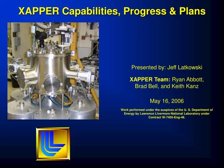
XAPPER Capabilities, Progress & Plans. Presented by: Jeff Latkowski XAPPER Team: Ryan Abbott, Brad Bell, and Keith Kanz May 16, 2006 Work performed under the auspices of the U. S. Department of Energy by Lawrence Livermore National Laboratory under Contract W-7405-Eng-48. Outline.

E N D
XAPPER Capabilities, Progress & Plans Presented by: Jeff Latkowski XAPPER Team: Ryan Abbott,Brad Bell, and Keith Kanz May 16, 2006 Work performed under the auspices of the U. S. Department of Energy by Lawrence Livermore National Laboratory under Contract W-7405-Eng-48.
Outline • Current capabilities • Progress since the ORNL HAPL meeting • Planned improvements JFL 05/16/06
9000 pulses @~1.5 J/cm2 Using our first high-quality ellipsoidalcondenser, pure tungsten can be damaged Significant damage is observed at a fluence of ~1.5 J/cm2 Unexposed JFL 05/16/06
Tungsten test matrix: 10,000 shotson powder met. 1.2 J/cm2 ~1.5 J/cm2 JFL 05/16/06
Current capabilities • Soft x-ray source: • Fluences of 0.25-1.25 J/cm2 (s ~ 10%) • ~50 ns 10-90% risetime • FWHM spot size is ~400 mm • Repetition rates ≤10 Hz • 106 pulses demonstrated, 105 pulse routine • Operational: • Fluence measurement conducted using CCD (or CMOS)camera in conjunction with calorimeter • Vacuum typically ~10-4 torr, then inject xenon for pinchand come up to ~3 mtorr • Samples actively heated up to 1000ºC (no active cooling) • Other diagnostics and analysis equipment: • In-chamber sample imaging (low magnification) • X-ray spectrometer • Photodiodes (fast and integrating) • PIE: SEM, TEM, Veeco, x-ray radiography, optical microscopy ~1.0 J/cm2 needed to heat 600C sample to peak surface temperature of 2500C JFL 05/16/06
600nm 1000nm 800 nm 1600 nm 500-1700nm 1200nm 1400nm Since the ORNL HAPL meeting,we have finalized our pyrometer design • Wavelengths of 0.6, 0.8, 1.0, 1.2, 1.4 and 1.6 mm selected • Using Avalanche Photodiodes (APDs): • Si APDs at 0.6, 0.8 and 1.0 mm • InGaAs APDs at 1.2, 1.4 and 1.6 mm • Each will be integrated into an amplifier • Able to reuse SiO2 fiber and feedthrufrom UCSD thermometer • Pyrometer head design uses 3 optics(63, -40 and 63 mm focal length) andis 98.9mm long; 100 mm field-of-view JFL 05/16/06
Calibration will be a big partof our pyrometer effort • Emissivity is both wavelength and temperature dependent • Past work has assumed that e(l1) = e(l2) • Okay assumption when operating at 0.7, 0.8 mm • Not a reasonable assumption for a wide range of wavelengths • We would see ~2x variation in e over our wavelengths of 0.6-1.6 mm • Emissivity ratios are notconstant with temperature Data for polished single crystal tungsten. JFL 05/16/06
Calibration, (Cont'd.) • To enable calibration, we are procuring a high-temperature sample heater (2500C) • Measurements will be taken on the same sample with the pyrometer head sitting in the same orientation to the actual measurement (other than the direction of gravity) • Calibration measurementswill be taken every 100Cfrom 1500-2500C • Post-processing will be usedto determine temperature vs.time from the 6-channel data JFL 05/16/06
Calibration, (Cont'd.) • HeatWave, Inc. is building the sample furnace: • Will mount to an 8” conflat • Water-cooled flange • 5-mm-diameter portionof sample viewable at 45 • (Very) hot test slatedfor end of June JFL 05/16/06
With the exception of the common opticsand minor items all parts are on order • Ordered: • Sample furnace • Bandpass filters (2 have arrived and exceed specifications) • Longpass filters (to be used as dichroics) • Si and InGaAs APDs • To be ordered soon: • Optical breadboard • Overall enclosure • Optical mounts and tubes • BK7/SiO2 lenses • Batteries (for detectors) • To be fabricated: • Light-tight enclosure for detectors (with filter mounts) • Top & bottom plates for calibration chamber (in progress) • Arrived/Available: • Signal cabling • Oscilloscopes • Optical fiber & feedthru We are on schedule for system assembly / checkout in early-July JFL 05/16/06
Other progress and/or improvements • We have completed a forward model of the pyrometer system, including tungsten emission vs. l and T, optical losses, and detector response • We have assembled a system to use as the calibration chamber • We are beginning to write procedures for the calibration furnace • Our safety paperwork is being updated • We are beginning to write the pyrometer data processing software • We have refined our CCD processing software (used to determine x-ray fluence) to account for path-dependent filter attenuation • Future exposure campaigns will include mass loss measurements (does this preclude us from putting multiple spots on a sample?) JFL 05/16/06
Summary • Since the last HAPL meeting, we have worked hard to design and procure the new pyrometer: • We expect to bring the pyrometer operational in July • We expect to have new sample exposures, with measured temperatures, in time for the next HAPL meeting • Planned sample priority is: (1) single crystal, (2) VPS tungsten, and (3) powder met. tungsten, (4) silicon carbide • We are holding off (for now) on the fabrication of a new ellipsoidal optic for use on XAPPER that would enable exposure of optical materials (low f, big spot) Right priority? JFL 05/16/06
The original thermometer has notworked for us for a variety of reasons • Original system used 200 mm fiber with 75 and 40 mm lenses: • Gave a 375 mm diameter field of view • XAPPER has a small spot size of~440 mm diameter • Gave temperature variations in field of view (a definite no-no for optical pyrometry) • Switched optics to 62 and 150 mm lenses: • Field of view reduced to 83 mm • Increased edge temperature to2450 ºC • Reduced field of view cuts signal by 20x, but 46% more solid-angle • Overall signal reduction of 14x JFL 05/16/06
Original thermometer, (Cont'd.) • Aligning the laser spot to the focused x-ray beam was impossible without manipulation under vacuum installed two-axis motorized gimbal system • Found a signal! Much celebration! Movie shows field of view with old thermometer head JFL 05/16/06
Original thermometer, (Cont'd.) • We moved onto a new sample to start collecting real data signal was gone! • Discovered that the heavily damaged sample had been reflecting pinch light into the thermometer head • Confirming experiment: blocked EUV beam with a plate of glass and still saw same (visible light) signal JFL 05/16/06
We have tried various fixes • Look for a dead-zone in the spectrum doesn't appear to be one • Temporal discrimination between pinch and emitted light pinch light persists too long • Vary angles not a real option (can’t get shallower angle; blackbody emission is lambertian, so signal would fall rapidly at steeper angles) • Look at the back side of a thin sample inadequate space All of these options assume that we have a good signal that gets drowned out by reflected pinch light. Instead, we see nothing until the material damages. Suppressing the pinch light won’t fix the underlying problem. JFL 05/16/06
3500 3000 2500 2000 1500 1000 10-9 10-7 10-5 10-3 10-1 Original thermometer, (Cont'd.) • Use thin sample (<5 mm) to keep material hot for "long" time (milliseconds): • Sit at lower temperature, lose by T4 (12-18x) • Able to count for ~1ms instead of ~100ns, win big (104x) • Unfortunately, the ripples inherent to a thin foil are quite similar to those resulting from surface damage we immediately see reflected pinch light JFL 05/16/06
Original thermometer, (Cont'd.) • Why doesn’t it work for us? Signal strength is just too low: • 700/800nm aren’t the best wavelengths for our target temperatures; plus, small spread forces narrow bandpass (10 vs. 40nm) filters, further reducing the possible signal • Simple analysis shows that blackbody emission getting to thermometer head (with Lambertian distribution) is only 1400-2100 p/ns in each band • Emissivity probably ~0.3 and filters transmission is ~50%, so we have200-300 p/ns • Uncoated fiber ends (and possibly optics) result in further reductions JFL 05/16/06
The XAPPER experiment is used to studydamage from rep-rated x-ray exposure • Source designed / built by PLEX LLC • Operates with xenon gas pinch to produce 80-150 eV x-rays • Operation possible at up to 10 Hz for millions of pulses Materialsample Condensingoptic Plasmapinch JFL 05/16/06