Download
1 / 10
100 likes | 357 Views
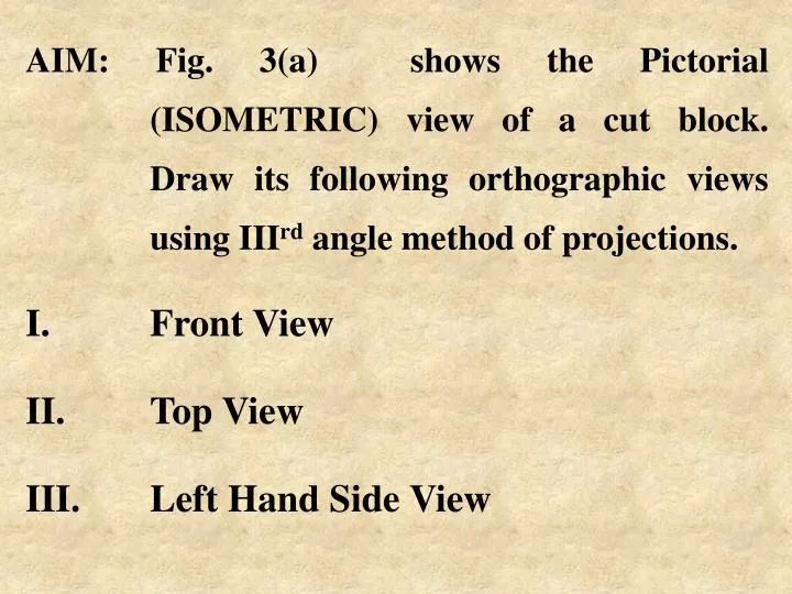
AIM: Fig. 3(a) shows the Pictorial (ISOMETRIC) view of a cut block. Draw its following orthographic views using III rd angle method of projections. Front View Top View Left Hand Side View. Y. Y. Y. H. 4. X. L. D. X. Z 1. 6. Fig 3(a). T.V. D. L. H. L.H.S.V. F.V. 2. Z 1. X.

E N D
AIM: Fig. 3(a) shows the Pictorial (ISOMETRIC) view of a cut block. Draw its following orthographic views using IIIrd angle method of projections. • Front View • Top View • Left Hand Side View
Y Y Y H 4 X L D X Z1 6 Fig 3(a) T.V. D L H L.H.S.V. F.V. 2 Z1 X Plane 4 turned up(above plane 2) Plane 6 turned side way(towards left side of plane 2) Fig 3(b)
Note : IIIrd angle means, the block is assumed behind 2, below 4 and inside 6, as in fig. 3(b) where the F.V. is projected on 2, seen in X direction, T.V. is projected on 4, seen in Y direction & L.H.S.V. is projected on 6, seen in Z1 direction
Fig. 3(c) shows turning of the planes 4 & 6 with their respective hinges, considering plane 2 as fixed plane. • It may be noted that :- • F.V. (X directional view) is on 2, T.V. (Y directional view) is on 4, while L.H.S.V (Z1 directional view) is on 6 • b) F.V is within L & H, T.V is within L & D, While L.H.S.V is within H & D. • c) The symbol for IIIrd angle method of projections is placed as shown on fig. 3(c)
4 T.V. Y X 6 2 L D H F.V. L.H.S.V Note :- XY line, boundary of planes 2,4,6 & hinges are not drawn, in actual otho. practice Fig. 3(c) Symbol here
AIM: Fig. 4(a) shows the Pictorial (ISOMETRIC) view of a cut block. Draw its following orthographic views using IIIrd angle method of projections. • Front View • Top View • Right Hand Side View
Y Y 4 X Y X Z2 D L T.V. Fig. 4(a) D L H H F.V. 2 R.H.S.V. 8 X Z2 Fig. 4(b) Planes 2, 4 & 8 are assumed as transparent
Note : IIIrd angle means, the block is assumed behind 2, below 4 and inside 8, as in fig. 4(b) where the F.V. is projected on 2, seen in X direction, T.V. is projected on 4, seen in Y direction & R.H.S.V. is projected on 8, seen in Z2 direction.
Fig. 4(c) shows turning of the planes 4 & 8 with their respective hinges, considering plane 2 as fixed plane. • It may be noted that :- • F.V. (X directional view) is on 2, T.V. (Y directional view) is on 4, while R.H.S.V (Z2 directional view) is on 8 • b) F.V is within L & H, T.V is within L & D, While R.H.S.V is within H & D. • c) The symbol for IIIrd angle method of projections is placed as shown on fig. 4(c) XY line & boundary of planes 2,4 & 8 are not drawn, in actual otho. practice
Note :- XY line, boundary of planes 1,3,7 & hinges are not drawn, in actual otho. practice. 4 D T.V. 8 Y X L H R.H.S.V. F.V. 2 Fig. 4(c) Symbol here