Download
1 / 16
190 likes | 532 Views
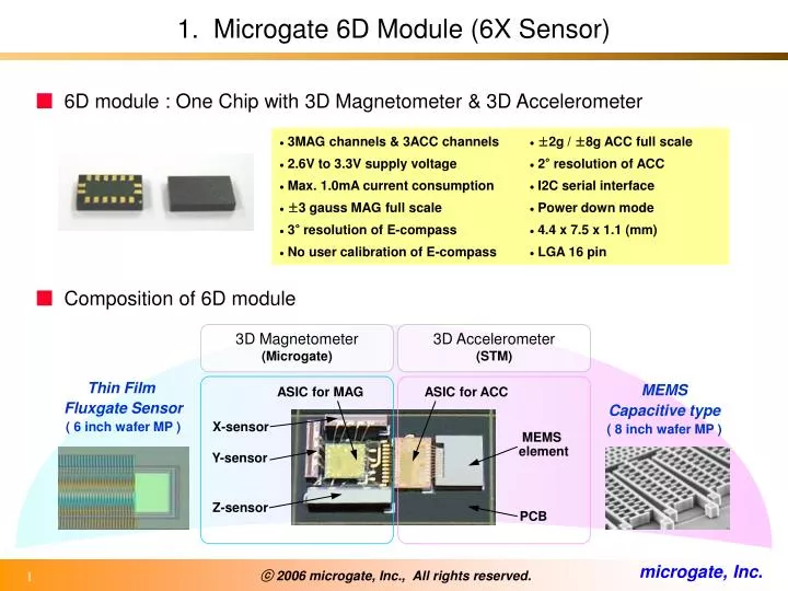
3MAG channels & 3ACC channels 2.6V to 3.3V supply voltage Max. 1.0mA current consumption ±3 gauss MAG full scale 3° resolution of E-compass No user calibration of E-compass. ±2g / ±8g ACC full scale 2° resolution of ACC I2C serial interface Power down mode 4.4 x 7.5 x 1.1 (mm)

E N D
3MAG channels & 3ACC channels • 2.6V to 3.3V supply voltage • Max. 1.0mA current consumption • ±3 gauss MAG full scale • 3° resolution of E-compass • No user calibration of E-compass • ±2g / ±8g ACC full scale • 2° resolution of ACC • I2C serial interface • Power down mode • 4.4 x 7.5 x 1.1 (mm) • LGA 16 pin 1. Microgate 6D Module (6X Sensor) ■ 6D module : One Chip with 3D Magnetometer & 3D Accelerometer ■ Composition of 6D module 3D Magnetometer (Microgate) 3D Accelerometer (STM) Thin Film Fluxgate Sensor ( 6 inch wafer MP ) MEMS Capacitive type ( 8 inch wafer MP ) ASIC for MAG ASIC for ACC X-sensor MEMS element Y-sensor Z-sensor PCB
D P P D 2. Thin Film Fluxgate Sensors for E-compass ■ Operation Principle of Fluxgate Sensors X & Y sensor items Z sensor Schematic diagram 1 bar type (Cf. conventional, 2 bar type) 4 block type ( Invention of new design ) • Voltage peak height (mV) : 14 ± 1 • Peak movement quantities : over ± Δ60 Electronic properties • Voltage peak height (mV) : 14 ± 1 • Peak movement quantities : over ± Δ20 Triangular wave (± 2V) into the fluxgate sensor Pick-up voltage output from the fluxgate sensor
Microgate E-compass Others VS High Low Absolute zero point 3. Features of Microgate E-compass ■ No User Calibration • Thin film fluxgate sensor can detect the absolute magnetic field quantities unlike other magnetic sensors ( Hall, MI, AMR, GMR ), which measure the relative difference values. • The magnetic field changes according to the location changes can be easily calibrated by an auto-calibration S/W. • Only ‘One time calibration’ is required at the electronic device manufacturers for the calibration of the magnets or magnetic field in the electronic devices. ■ Provision of the Best & the Optimized Resolution • 100 cardinals resolution is possible. • The regulation of the cardinal points is, of course, possible. (Ex. ; 120, 64, 32, 16, 8, 4 cardinals) ■ Reliable Accuracy • Fluxgate e-compass can recognize the magnetic north pole at every moment, regardless of the location changes, temperature changes, and working time passage.
4. Direction Decision Algorithm Final direction information 5D(/6D) operating S/W for the posture compensation of the cars & the phones This operation is carried out by using our providing S/W, which will be embedded in the host CPU The output data form is the numeric angle values, ‘θ’, between the magnetic north pole and the base line of the chip (or the electronic devices) Primary direction information 3D MAG operating S/W Inclination & Tilt information of 6D module or electronic device XMAG YMAG ZMAG XACC YACC ZACC 6D Module 3D Magnetometer 3D Accelerometer 6 data serial output through I2C interface after power on
Pedometer Navigation (Real-time direction information) Motion dialing Motion controlled game Menu scroll & Document browsing Camera image stabilization 5. Applications of 6D Module ■Mobile Phone & Navigator ■Functional Systems • • Robot control : Robot for industry and consumer electronics • Space data input device : Presenter (TV & PC), Mouse • Optical image stabilization : Digital camera, Vehicle camera • Others ; Fee-fall protections, Anti-theft application, etc. ※ In case of motion detection application, the separate algorithm developments are required.
D. Magneto-Impedance Sensor ■ MI Sensor (Aichi steel) • When high frequency applied along the wire, the surface of wire • becomes insulator. It is called skin depth effect. • MI use skin depth changes of wire surface which can be varied by • the external magnetic field changes. • MI has a reliability problem of the voltage output position. • And, Uniformity of the every wire surface structure must be guaranteed. • MI sensor is a bulk assembled sensor MP speed & Yield decrease. • Z-sensor height problem thick chip • High frequency usage Noise occurrence
E. Hall-effect Sensor ■ Hall Sensor (Asahi-Kasei) • The Hall sensor can check the voltage difference (VH) in the semiconductor Hall films. • The Hall voltages are made by charging up of electrons due to the magnetic field application. • The measured VH is not an absolute value, but relative values. • Therefore, zero point reset of output voltage is required, for it being used as an e-compass. • The requirement of DOE algorithm suggested by Asahi-Kasei and motion added calibration represent that • Hall can not find the zero point or reference point of the magnetic field, if it were not for ceaseless calibration. • Hall also need temperature compensation because the increase of temperature increases the electron motilities. • The partition of the Hall voltage difference is not accurate. Therefore, the resolution power is not high.
Major loop R1 R2 R3 R4 Minor loop R = R0 + ΔR0 cos2θ Circuit F. Anisotropic Magneto-Resistive Sensor ■ AMR Sensor (Honeywell) • The MR effect means the resistance drop of the NiFe films according to the existence of the extra magnetic field. • The AMR film must be made to have a directional magnetization by applying high magnetic field. • When the external magnetic field (ex. The earth’s magnetic field) is applied with an angle (θ), the magnetization • direction in the film is rotated. • In this case, the resistance of the film decrease and the resistance changes is around -2%. • The resistance changes (~10-6 order) has the relation with the external magnetic field indirectly. • This is the operating principle of the AMR sensor. • <Problems of AMR sensor> • It must be maintained the initial directional magnetization of the NiFe films, however, it diverge as times goes by. • When times goes by, or temperature increases, the directional magnetization lose its directionality, therefore, • calibration and additional magnetization reset is required. • According to Honeywell, high volt (~40 volt) is required by using a solenoid coil in the AMR sensor for renew reset. • The usage of minor loop. The trace of the minor loop is not reproducible. Reliability decrease and calibration • required
Top Electrode (Ta or Ru) CoFe/NiFe, CoFe, NiFe Cu CoFe Anti-Ferro Magnet (IrMn, PtMn) Under Layer (NiFe) Bottom Electrode (Ta) Si Wafer GMR Sensor vertical structure Operating principle Signal output (Resistivity change) G. Giant Magneto-Resistive Sensor ■ GMR Sensor (Alps, Yamaha, Hitachi) • GMR is also operated by changing the magnetization direction in the film like an AMR. • At initial stage, the spin directions of two magnetic layers are anti-parallel. • When the external magnetic field is applied on GMR films as shown in the 2nd figure, the magnetization align • parallel. In this case, the resistance decrease. • <Problems of GMR sensor> • Almost the same problems of the previous mentioned AMR sensor still exist in GMR sensor. • If GMR can notice the absolute 0 value of the magnetic field, there will be no need of using auto calibration S/W. • The existence of the auto calibration S/W implies that GMR also can not measure the absolute value of the • magnetic field • The resolution of GMR is higher than that of AMR, because the MR ratio of GMR is 10%~40% according to the • manufacturing technology. (Cf. MR ratio of AMR is around 2%)
NiFe bar H. Conventional Fluxgate Sensor ■ Conventional 2-bar Type Fluxgate Sensor ■ PCB Fluxgate Sensor (Samsung, AP1systems) • Bulk assembled sensor Z-sensor manufacturing of short height is impossible.
I. Magnetic Properties of Thin Film Fluxgate ■ The Origination of Isolated Peak & Peak Shift in Microgate’s Fluxgate Sensor Hs Hc • The hysteresis loop with extremely high squareness • at e-compass operation frequency (12KHz) • is absolutely required. • Small coercivity (Hc) & Fast saturation (Hs) at high • frequency range is needed to make an isolated peak. • Voltage peak height = - η•(dM/dt) • If the inclination of loop decrease slightly, (dM/dt) • decrease drastically and voltage peak finally disappear. • fluxgate become a kind of transformer like bulk • or PCB fluxgate Peak positions without any external magnetic field time Peak shift according to the (+)DC magnetic field (DC magnetic field meansthe earth’s magnetic field) Peak shift according to the (-)DC magnetic field time
J. Output Signal Changes due to the Applied Magnetic Field ■ Peak Shift Occurrence due to the External Magnetic Field • Isolated voltage peak shift • Peak-to-peak distance (scale : µsec) can • be measured by using ASIC. • The real earth’s magnetic field is around • ±0.5 gauss. • When the earth’s magnetic field is applied • on the fluxgate, the peak shift distance will • be the half of the peak shift distance shown • in photograph. (±1.0 gauss were applied • to make it easy to notice). Applied field ( +1.0 gauss ) C No external field (standard state) A Applied field (-1.0 gauss) • Magnetic field detection range • The detection range can be changed • by changing the fluxgate design. B ~±1.0 gauss ~±3.5 gauss
K. Block Diagrams of 6D module ■3D E-compass ■3D Accelerometer