Download
1 / 20
210 likes | 417 Views
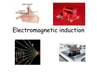
ELECTROMAGNETIC INDUCTION. Magnetic Flux Faraday’s Experiments Faraday’s Laws of Electromagnetic Induction Lenz’s Law and Law of Conservation of Energy Expression for Induced emf based on both laws Methods of producing induced emf a) By changing Magnetic Field

E N D
ELECTROMAGNETIC INDUCTION • Magnetic Flux • Faraday’s Experiments • Faraday’s Laws of Electromagnetic Induction • Lenz’s Law and Law of Conservation of Energy • Expression for Induced emf based on both laws • Methods of producing induced emf • a) By changing Magnetic Field • b) By changing the Area of the Coil (Motional emf) • c) By changing the Relative Orientation of the coil with • the Magnetic Field • Eddy Currents • Self Induction and Self Inductance • Mutual Induction and Mutual Inductance • Additional Information Presented by A. Rajput, PGT(Physics), K V, AFS, Bareilly
dΦ = B . ds = B.ds. Direction of ds is along the normal to the surface and is unit normal vector. B θ Φ = B . A = B.A. n n n n Magnetic Flux (Φ): Magnetic Flux through any surface is the number of magnetic lines of force passing normally through that surface. It can also be defined as the product of the area of the surface and the component of the magnetic field normal to that surface. B cos θ ds dΦ = B . ds cos θ Φ = B . A cos θ Positive Flux: Magnetic Flux is positive for0° ≤ θ < 90°&270° < θ ≤ 360° Zero Flux: Magnetic Flux is zero forθ = 90°&θ = 270° Negative Flux: Magnetic Flux is negativefor90° < θ < 270° Flux is maximum whenθ = 0°andisΦ = B . A
Φ = B . Acos θ Magnetic Flux across a coil can be changed by changing : 1) the strength of the magnetic field B 2) the area of cross section of the coil A 3) the orientation of the coil with magnetic field θor 4) any of the combination of the above * Magnetic flux is a scalar quantity. * SI unit of magnetic flux is weber or tesla-metre2 or ( wb or Tm2). * cgs unit of magnetic flux is maxwell. * 1 maxwell = 10-8 weber * Magnetic flux (associated normally) per unit area is called Magnetic Flux Density or Strength of Magnetic Field or Magnetic Induction (B).
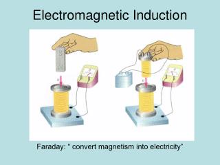
S N N N S S N N S S S N Faraday’s Experiment - 1: G G G G
S N N S G Magnetic flux linked with the coil changes relative to the positions of the coil and the magnet due to the magnetic lines of force cutting at different angles at the same cross sectional area of the coil.
Observe: i) the relative motion between the coil and the magnet ii) the induced polarities of magnetism in the coil iii) the direction of current through the galvanometer and hence the deflection in the galvanometer iv) that the induced current (e.m.f) is available only as long as there is relative motion between the coil and the magnet Note:i) coil can be moved by fixing the magnet ii) both the coil and magnet can be moved ( towards each other or away from each other) i.e. there must be a relative velocity between them iii) magnetic flux linked with the coil changes relative to the positions of the coil and the magnet iv) current and hence the deflection is large if the relative velocity between the coil and the magnet and hence the rate of change of flux across the coil is more
N N N S S S E E S N Faraday’s Experiment - 2: When the primary circuit is closed current grows from zero to maximum value. During this period changing, current induces changing magnetic flux across the primary coil. This changing magnetic flux is linked across the secondary coil and induces e.m.f (current)in the secondary coil. Induced e.m.f (current) and hence deflection in galvanometer lasts only as long as the current in the primary coil and hence the magnetic flux in the secondary coil change. P S K G P S K G
When the primary circuit is open current decreases from maximum value to zero. During this period changing current induces changing magnetic flux across the primary coil. This changing magnetic flux is linked across the secondary coil and induces current (e.m.f) in the secondary coil. However, note that the direction of current in the secondary coil is reversed and hence the deflection in the galvanometer is opposite to the previous case. Faraday’s Laws of Electromagnetic Induction: I Law: Whenever there is a change in the magnetic flux linked with a circuit, an emf and hence a current is induced in the circuit. However, it lasts only so long as the magnetic flux is changing. II Law: The magnitude of the induced emf is directly proportional to the rate of change of magnetic flux linked with a circuit. Eα dΦ / dt E = k dΦ / dt E = dΦ / dt E = (Φ2 – Φ1) / t (where k is a constant and units are chosen such that k = 1)
Lenz’s Law: The direction of the induced emf or induced current is such that it opposes the change that is producing it. i.e. If the current is induced due to motion of the magnet, then the induced current in the coil sets itself to stop the motion of the magnet. If the current is induced due to change in current in the primary coil, then induced current is such that it tends to stop the change. Lenz’s Law and Law of Conservation of Energy: According to Lenz’s law, the induced emf opposes the change that produces it. It is this opposition against which we perform mechanical work in causing the change in magnetic flux.Therefore, mechanical energy is converted into electrical energy. Thus, Lenz’s law is in accordance with the law of conservation of energy. If, however, the reverse would happen (i.e. the induced emf does not oppose or aids the change), then a little change in magnetic flux would produce an induced current which would help the change of flux further thereby producing more current. The increased emf would then cause further change of flux and it would further increase the current and so on.This would create energy out of nothing which would violate the law of conservation of energy.
Expression for Induced emf based on both the laws: E = - dΦ / dt E = - (Φ2 – Φ1) / t And for ‘N’ no. of turns of the coil, E = - N dΦ / dt E = - N (Φ2 – Φ1) / t Expression for Induced current: Note: Induced emf does not depend on resistance of the circuit where as the induced current and induced charge depend on resistance. I = - dΦ / (R dt) Expression for Charge: dq / dt = - dΦ / (R dt) dq = - dΦ / R Methods of producing Induced emf: • By changing Magnetic Field B: • Magnetic fluxΦ can be changed by changing the magnetic field B and hence emf can be induced in the circuit (as done in Faraday’s Experiments).
2. By changing the area of the coil A available in Magnetic Field: Magnetic fluxΦ can be changed by changing the area of the loop A which is acted upon by the magnetic field B and hence emf can be induced in the circuit. P’ Q’ P Q v l B v.dt R’ S’ R S dΦ = B.dA = B.l.v.dt E = - dΦ / dt E = - Blv dA I The loop PQRS is slided into uniform and perpendicular magnetic field. The change (increase) in area of the coil under the influence of the field is dA in time dt. This causes an increase in magnetic flux dΦ. The induced emf is due to motion of the loop and so it is called ‘motional emf’. If the loop is pulled out of the magnetic field, then E = Blv The direction of induced current is anticlockwise in the loop. i.e. P’S’R’Q’P’ by Fleming’s Right Hand Rule or Lenz’s Rule.
Magnetic Field (B) Force(F) ElectricCurrent (I) According Lenz’s Rule, the direction of induced current is such that it opposes the cause of changing magnetic flux. Here, the cause of changing magnetic flux is due to motion of the loop and increase in area of the coil in the uniform magnetic field. Therefore, this motion of the loop is to be opposed. So, the current is setting itself such that by Fleming’s Left Hand Rule, the conductor arm PS experiences force to the right whereas the loop is trying to move to the left. Against this force, mechanical work is done which is converted into electrical energy (induced current). NOTE: If the loop is completely inside the boundary of magnetic field, then there will not be any change in magnetic flux and so there will not be induced current in the loop. Fleming’s Right Hand Rule: If the central finger, fore finger and thumb of right hand are stretched mutually perpendicular to each other and the fore finger points to magnetic field, thumb points in the direction of motion (force), then central finger points to the direction of inducedcurrent in the conductor.
S P θ B Φ = N B A cos ωt R Differentiating w.r.t. t, dΦ / dt = - NBAω sin ωt E = - dΦ / dt E = NBAω sin ωt E = E0 sin ωt(where E0 = NBAω is the maximum emf) Q n 3. By changing the orientation of the coil (θ) in Magnetic Field: Magnetic flux Φ can be changed by changing the relative orientation of the loop (θ) with the magnetic field B and hence emf can be induced in the circuit. Φ = N B A cos θ At time t, with angular velocity ω, θ = ωt (at t = 0, loop is assumed to be perpendicular to the magnetic field and θ = 0°) ω
π/2 π/2 π π 3π/2 3π/2 2π 2π 5π/2 5π/2 3π 3π 7π/2 7π/2 4π 4π t t E = E0 cos ωt E The emf changes continuously in magnitude and periodically in direction w.r.t. time giving rise to alternating emf. If initial position of the coil is taken as 0°, i.e. normal to the coil is at 90° with the magnetic field, thenθ becomes θ + π/2or ωt + π/2 E0 0 θ = ωt T/4 T/2 3T/4 T 5T/4 3T/2 7T/4 2T E E0 So, alternating emf and consequently alternating current can be expressed in sin or cos function. 0 θ = ωt T/4 T/2 3T/4 T 5T/4 3T/2 7T/4 2T This method of inducing emf is the basic principle of generators.
B Eddy Currents or Foucault Currents: The induced circulating (looping) currents produced in a solid metal due to change in magnetic field (magnetic flux) in the metal are called eddy currents. • Applications of Eddy Currents: • In induction furnace eddy currents are used for melting iron ore, etc. • In speedometer eddy currents are used to measure the instantaneous speed of the vehicle. • In dead beat galvanometer eddy currents are used to stop the damping of the coil in a shorter interval. Metallic Block Eddy Currents • In electric brakes of the train eddy currents are produced to stop the • rotation of the axle of the wheel. • 5. In energy meters (watt – meter) eddy currents are used to measure the • consumption of electric energy. • In diathermy eddy currents are used for localised heating of tissues in • human bodies.
Self Induction: Self Induction is the phenomenon of inducing emf in the self coil due to change in current and hence the change in magnetic flux in the coil. The induced emf opposes the growth or decay of current in the coil and hence delays the current to acquire the maximum value. Self induction is also called inertia of electricity as it opposes the growth or decay of current. Self Inductance: Φα I orΦ = LI If I = 1, then L = Φ (where L is the constant of proportionality and is known as Self Inductance or co-efficient of self induction) Thus, self inductance is defined as the magnetic flux linked with a coil when unit current flows through it. Also, E = - dΦ / dt or E = - L (dI / dt) If dI / dt = 1, then L = E Thus, self inductance is defined as the induced emf set up in the coil through which the rate of change of current is unity.
l I0 W = ∫ L I dI = ½ LI02 0 SI unit of self inductance is henry (H). Self inductance is said to be 1 henry when 1 A current in a coil links magnetic flux of 1 weber. or Self inductance is said to be 1 henry when unit rate of change of current (1 A / s) induces emf of 1 volt in the coil. Self inductance of a solenoid: A Magnetic Field due to the solenoid is B = μ0nI Magnetic Flux linked across one turn of the coil is Φ per turn = B A = μ0nIA = μ0NIA / l Magnetic Flux linked across N turns of the coil is Φ = μ0N2IA / l But,Φ = LI So, L = μ0N2A / l = μ0n2Al I Energy in Inductor: Small work done dW in establishing a current I in the coil in time dt isdW = - EI dt dW = LI dI(since E = -L(dI / dt)
Mutual Induction: Mutual Induction is the phenomenon of inducing emf in the secondary coil due to change in current in the primary coil and hence the change in magnetic flux in the secondary coil. Mutual Inductance: Φ21α I1 or Φ21 = MI1 If I1 = 1, then M = Φ (where M is the constant of proportionality and is known as Mutual Inductance or co-efficient of mutual induction) Thus, mutual inductance is defined as the magnetic flux linked with the secondary coil when unit current flows through the primary coil. Also, E2 = - dΦ21 / dt or E2= - M (dI1 / dt) If dI1 / dt = 1, then M = E Thus, mututal inductance is defined as the induced emf set up in the secondary coil when the rate of change of current in primary coil is unity. SI unit of mututal inductance is henry (H). Mutual inductance is said to be 1 henry when 1 A current in the primary coil links magnetic flux of 1 weber across the secondary coil.or Mutual inductance is said to be 1 henry when unit rate of change of current (1 A / s) in primary coil induces emf of 1 volt in the secondary coil.
G I1 l Mutual inductance of two long co-axial solenoids: Magnetic Field due to primary solenoid is B1 = μ0n1I1 Magnetic Flux linked across one turn of the secondary solenoid is Φ21 per turn = B1 A = μ0n1I1A = μ0N1I1A / l Magnetic Flux linked across N turns of the secondary solenoid is Φ21 = μ0N1N2I1A / l But, Φ21 = M21I1 M21 = μ0N1N2A / l = μ0n1n2Al lllly M12 = μ0N1N2A / l = μ0n1n2Al S A P For two long co-axial solenoids of same length and cross-sectional area, the mutual inductance is same and leads to principle of reciprocity. M = M12 = M21
Additional Information: • If the two solenoids are wound on a magnetic core of relative permeability μr, then • M = μ0μrN1N2A / l • If the solenoids S1 and S2 have no. of turns N1 and N2 of different radii r1 and r2 (r1 < r2), then • M = μ0μrN1N2 (πr12)/ l • Mutual inductance depends also on the relative placement of the solenoids. • Co-efficient of Coupling (K) between two coils having self-inductance L1 and L2 and mutual inductance M is • K = M / (√L1L2) Generally, K < 1 • If L1 and L2 are in series, then L = L1 + L2 • If L1 and L2 are in parallel, then (1/L) = (1/L1) + (1/L2)