Download
1 / 17
200 likes | 343 Views
Study on the Corrosion of Negative Straps in VRLA Batteries. C. Z. Qiu [a] , A. J. Li [a] , L. P. Tang [a] , C. L. Dou [a] , W. Zhang [b] , D. J. Zhang [b] , S.Chen [b] , G. M. Xiao [b] , S.G.Peng [b] ,W.W.Wei [b] ,H.Wang [b] .H. Y. Chen [a] *

E N D
Study on the Corrosion of Negative Straps in VRLA Batteries C. Z. Qiu[a], A. J. Li[a], L. P. Tang[a],C. L. Dou[a], W. Zhang[b], D. J. Zhang [b] , S.Chen[b] , G. M. Xiao[b], S.G.Peng[b],W.W.Wei[b],H.Wang[b].H. Y. Chen[a]* a.School of Chemistry and Environment, South China Normal University, Guangzhou,Guangdong 510006,Chinab.Zhuzhou Smelter Group Co,Ltd,Zhuzhou,Hunan 412004,China)
Contents 1 Introduction 2 Experimental 3 Results and discussion 4 Conclusion
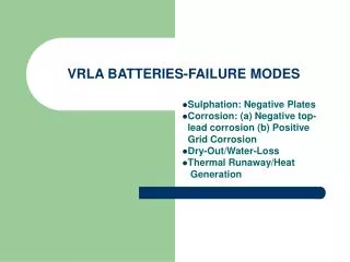
1. Introduction • There are many reports about improving the properties of the alloys as the positive grids in lead-acid batteries. However, studies on the negative straps in lead-acid batteries are scarce. In VRLA batteries, because the straps are not submerged in sulfuric acid, they cannot be cathodically protected. Without the cathodic protection, PbSO4 formed in the oxygen recombination cycle was not converted back to lead, and sulfation corrosion proceeds to ultimately cause the strap fracture.
1. Introduction • Two main types of negative strap alloys were used in lead-acid batteries: one is the lead-antimony alloys, the other was the lead–tin alloys. But antimony is poisonous, it is not suggested that lead-antimony be used as negative strap alloy. Therefore, the lead–tin alloy is relatively better. There are literature data for the application of Se as an alloying additive to Pb-Sn alloys. But most studies were on the alloys’elecelectrochemical behavior ,but little was about the alloys’ metallographic structure.The microstructures of the alloys and the structure of the corrosion layers play an important role in their properties. So our aim is to further compare the metallographic structure of Pb-Sn and Pb-Sn-Se alloys and simulate the corrosion atmosphere of the negative straps to compare their corrosion properties.
2. Experimental • The metallographic samples in forms of rod alloys were mechanically polished by 1000# and 2000# SiC emery papers. Then the polished section was chemically polished using a 1:1 (by volume) acetic acid/hydrogen peroxide solution, and etched with a solution containing 9 g of ammoniummolybdate, and 15 g of citric acid in 90 g of distilled water. The structure of the alloys was observed using a Nikon LV-UEPT polarizing microscope. • The metal phases were identified by X-ray diffraction, XRD analysis over a scan range of 10–90°at a rate: of 0.01°per 0.4 s.
2.Experimental • Corrosion test——A scheme of the experimental setup is presented in Fig. 1. Investigated samples (the positive electrodes were pure lead, the negative electrodes were investigated samples) were 7.0 cm long, 1 cm wide, and 0.15 cm thick. Absorbing glass mats (AGM) were placed in the glasses and soaked in 4.5 M H2SO4 solution.1 cm of the length of the samples were inserted into the AGM and 2-6cm were out of the solution. The top of the glasses were covered with films. All of the glasses were placed in the same constant temperature water bath which was heated at 60 °C, and the samples were in series electrified with constant current 0.06 A for a month.
3. Results and discussion • 3.1 Microstructure of the Pb-0.8wt%Sn and Pb-0.8 wt %Sn-Se alloys • 3.2 XRD patterns of Pb-0.8wt.%Sn and • Pb-0.8%Sn-Se alloys • 3.3 Corrosion test for Pb-0.8%Sn and • Pb-0.8%Sn-Se alloys
3.1 Microstructure of Pb-0.8 wt %Sn-Se alloys Pb-0.8wt%Sn-Se alloys alloys (with Se>0.02wt.%) show fine grain size and regular grain boundaries by comparing with that of Pb-0.8wt%Sn. As a result ,the introduction of Se may protect lead alloy from recrystallization and improve its structure stability. Fig. 2. Micrographs of Pb-0.8%Sn and Pb-0.8%Sn-Se alloys with different Se contents. (a) Pb-0.8wt.%Sn;(b)Pb-0.8wt.%Sn–0.01wt.%Se;(c)Pb-0.8wt.%Sn–0.02wt.%Se;(d)Pb-0.8wt.%Sn- 0.03wt.%Se; (e)Pb-0.8wt.%Sn–0.05wt.%Se; (f) Pb-0.8wt.%Sn–0.10wt.%Se
3.2 XRD patterns of Pb-0.8wt.%Sn and Pb-0.8%Sn-Se alloys Fig3. XRD patterns of Pb-0.8%Sn and Pb-0.8%Sn-Se alloys The results from fig.3 feature a characteristic peak of lead and there is no indication of the presence of other crystal phases.
3.2 XRD patterns of Pb-0.8wt.%Sn and Pb-0.8%Sn-Se alloys The following relation exists among the interplanar spacingd, the indices of the crystallographic planes H, K, L and the lattice parameter. 1/d2=1/v2[H2b2c2sin2α+K2a2c2sin2β+L2a2b2sin2γ+ 2HKabc2(cosαcosβ-cosγ)+2KLa2bc(cosβcosγ-cosα)+HLab2c(cosαcosγ-cosβ)] (1) Where: v=abc(1+2cosαcosβcosγ-cos2α-cos2β-cos2γ)1/2 For a cubic system, Eq. (1) should read: 1/d2=(H2+ K2+L2)/a2 (2)
3.2 XRD patterns of Pb-0.8wt.%Sn and Pb-0.8%Sn-Se alloys The cell parameters of six samples were calculated on the basis of Eq. (2) and the parameters were listed in Table 1. The results are as follows: a1=4.974nm, a2=4.924 nm, a3=4.936nm, a4 =4.913 nm, a5=4.902, a6=4.919657. The cell parameters of the Pb-0.8%Sn-Se alloys are less than those of lead, which indicates that finer grains are obtained. Table1.Parameters of main diffraction peaks of XRD patterns of Pb-0.8%Sn and Pb-0.8%Sn-Se alloys
3.3 Corrosion test for Pb-0.8%Snand Pb-0.8%Sn-Se alloys Fig.4. SEM micrographs of the structure of the corrosion layers formed at different heights on Pb-0.8%Sn and Pb-0.8%Sn-Se electrodes inserted in AGM soaked in 4.5 M H2SO4 solutions. ((A)Pb-0.8wt.%Sn;(B)Pb-0.8wt.%Sn–0.01wt.%Se;(C)Pb-0.8wt.%Sn–0.03wt.%Se;(D)Pb-0.8wt.%Sn-0.05wt.%Se)
3.3 Corrosion test for Pb-0.8%Snand Pb-0.8%Sn-Se alloys Fig.4. SEM micrographs of the structure of the corrosion layers formed at different heights on Pb-0.8%Sn and Pb-0.8%Sn-Se electrodes inserted in AGM soaked in 4.5 M H2SO4 solutions. ((A)Pb-0.8wt.%Sn;(B)Pb-0.8wt.%Sn–0.01wt.%Se;(C)Pb-0.8wt.%Sn–0.03wt.%Se;(D)Pb-0.8wt.%Sn-0.05wt.%Se)
3.3 Corrosion test for Pb-0.8%Sn and Pb-0.8%Sn-Se alloys The SEM micrographs reveal the differences in the morphology of the corrosion layers between the Pb-0.8%Sn and Pb-0.8%Sn-Se alloys. A loose and porous corrosion layer is formed on Pb-0.8%Sn, but a compact corrosion layer with fine corroded products can be observed on the Pb-0.8%Sn alloys. The corrosion layer becomes more compact and the corroded products become finer with the addition of Se. The compact corrosion layer of Pb-0.8%Sn alloys can reduce the further corrosion of inner lead alloys.
4. Conclusions (2) According to the calculation of d value from the XRD patterns of Pb-0.8%Sn and Pb-0.8%Sn-Se alloys, it is possible to conclude that finer grains are obtained with the addition of Se. (3) The corrosion test indicated that the corrosion products of Pb-Sn-Se alloys are fine and compact, and the adding of Se may reduce the further penetrable corrosion of inner lead alloys (1) The fine grain size and regular grain boundaries obtained in Pb-0.8%Sn-Se alloys (with Se≥0.02wt.%) may protect the lead alloy from recrystallization.