Download
1 / 21
250 likes | 489 Views
Space structures. 1. Mechanical behaviour of structural materials and structures for aerospace. Prof. P. Gaudenzi Università di Roma La Sapienza, Rome Italy paolo.gaudenzi@uniroma1.it. THE STRUCTURAL SYSTEM OF AN AIRCRAFT/ SPACECRAFT.

E N D
Space structures 1. Mechanical behaviour of structural materials and structures for aerospace Prof. P. Gaudenzi Università di Roma La Sapienza, Rome Italy paolo.gaudenzi@uniroma1.it
THE STRUCTURAL SYSTEM OF AN AIRCRAFT/ SPACECRAFT • Structure: set of mechanical components or assemblies designed to sustain loads or pressures, provide stiffness or stability or provide support or containment. • ECSS 30 2b Definition • The structural system of a spacecraft has three main functions: • To provide the support of all the other subsystem and materialize the geometry of the spacecraft and its payloads; • To guarantee the necessary STRENGTH to survive all phases of the spacecraft life (in particular the most critical: e.g. the launch) without failures.
THE STRUCTURAL SYSTEM OF A SPACECRAFT (2) • 3. To keep the structural STIFFNESS in certain limits to guarantee the operational functionality of the overall system and avoid coupled resonant responses (e.g. between a satellite and its launcher). • Since the cost of mass is very critical in an aerospace mission, the structural system should be optimized with respect to mass both in terms of material and in terms of the optimal structural geometries. Structural problems affect also other subsystems (e.g. propulsion, attitude and orbital control, on board data handling, TTC) and the payload itself. In fact every component of a spacecraft needs to withstand the mission environment and a structural failure could occur in a component of the system and might be critical for the success of the mission.
FORCE / DISPLACEMENT DIAGRAM OF A BAR IN TENSION A metallic material has constitutive law characterized by an elastic range up until a yield limit, then a plastic phase up until an ultimate limitσu (STRENGTH). Elastic behaviour: the structural systems subjected to an external loading progressively deforms and recovers its original shape returning back all the energy that was encorporated during the loading phase.
HOOKE’S LAW A linearbehaviour characterizes most of structural materials; in the 1D case: σ = E εHooke’s Law E= tan α E: Young’s modulus (STIFFNESS). In practice a unit load is applied to a bar ad the deformation is measured: the inverse of such a value is the Young’s modulus. During the loading of the bar its section shrinks:
FAILURE CRITERIA • In presence of biaxial loading the failure can occur at a value less than the uniaxial failure load. • Relations between the stress components express the condition of failure in presence of a multiaxial loading (VON MISES, TRESCA CRITERIA). Special care should be devoted to cases of anisotropic material (e.g. carbon fiber reinforced plastics).
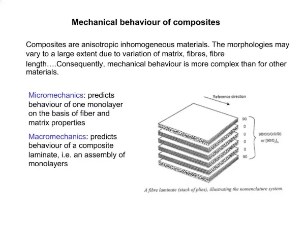
FRACTURE Fracture has to be evaluated as one of the main failure mechanisms in a structural material. As well known crack opening could occur according to different opening modes, regulated by different critical intensity factor. For composite materials openings could occurr due to voids encapsulated between layers, creating an artificial delamination. Delamination is also a possible failure mode of composites.
THERMOELASTIC BEHAVIOUR Structures (generally) expand when heated ΔT jump of temperature at a point Stress produced by thermal action
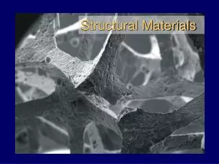
TYPICAL FEATURES OF STRUCTURAL MATERIALS FOR SPACE APPLICATIONS
STRUCTURAL BEHAVIOUR: BAR IN TENSION Basic experiment: a cable (or a bar) in tension Equilibrium of the infinitesimal element
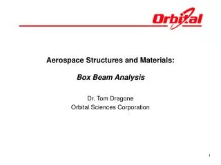
STRUCTURAL BEHAVIOUR: PURE BENDING OF A BEAM In order to produce a moment, σ has to vary along the section Best use of material: the optimal section is a double T I Moment of inertia around y The distribution of σ is linear along the thickness.
STRUCTURAL BEHAVIOUR: TORSION OF A BEAM To produce a torque MT the direction of the shear stress has to vary along the section In a way similar to the bending case it can be shown that the best section has a circular thin walled section *(Not applicable for not circular section)
MEMBRANE AND FLEXURAL BEHAVIOUR How can lateral loads be sustained by a unidimensional structure? Shear + bending membrane Variation of geometry but uniform σ on the section
PLATES, SHELLS, MEMBRANES PLATE MEMBRANE (easy to be bent) There could be a combination of membrane and plates
THIN WALLED STRUCTURES Membrane behavior is always preferred: the material is used in the most effective way. Closed thin walled sections are preferrably used in aerospace structures membrane bending cylinders spheres
BUCKLING AND STABILITY (1) In previous examples the equilibrium configuration is the original one. Sometimes the equilibrium could be also reached in a different configuration. Moreover it could happen that in presence of a slightly different geometry of the body or of the applied loads the equilibrium is not maintained. The sensitivity of the capability of mantaining an equilibrium configuration is studied by the theory of stability. The most famous example of unstable equilibrium is the buckling of a beam under compression, studied by Euler. By subjecting the beam at increasing P, for a certain critical value of P (Eulerian buckling load) the original equilibrium configuration becomes unstable and equilibrium is reached in a deformed configuration.
BUCKLING AND STABILITY (2) The buckling loads depends upon the geometry of the section (I) the material (E), the overall geometry (L) of the structure and the boundary conditions. For simply supported beams: Plates under compression or shear could have stability problems Buckling has consequences both on STIFFNESS (a flexible structure has strong displacements) and on STRENGTH. In fact, especially in bending behavior, the failure of the material (yielding or ultimate load) can be reached in the deformed configuration of equilibrium or, even worse, in absence of equilibrium.
CONCLUDING REMARKS Function of the structural system: materialisation of geometry and support, stiffness, strength, low density Material behaviour – main failure modes Structural behaviour Stress analysis, Dynamics, Stability, Thermoelasticity