Download
1 / 21
210 likes | 364 Views
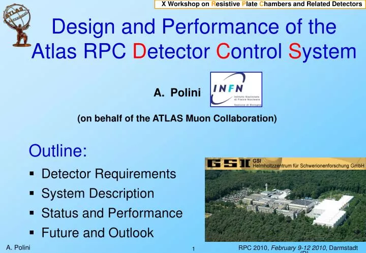
X Workshop on R esistive P late C hambers and Related Detectors. Design and Performance of the Atlas RPC D etector C ontrol S ystem. Polini (on behalf of the ATLAS Muon Collaboration). Outline: Detector Requirements System Description Status and Performance Future and Outlook. LHC.

E N D
X Workshop on Resistive Plate Chambers and Related Detectors Design and Performance of theAtlas RPC Detector Control System • Polini (on behalf of the ATLAS Muon Collaboration) Outline: • Detector Requirements • System Description • Status and Performance • Future and Outlook
LHC The ATLAS Detector Barrel region F 25 meters diameter Endcap region Endcap region 44 meters length
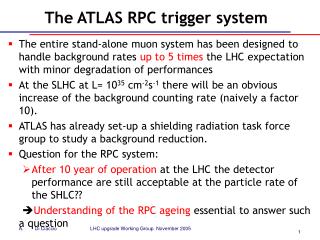
ATLAS RPC System |h| < 1.1 370k ch, 1100 units, 3650 m2 det. area used for Trigger and Readout (, ) BO RPC3 CONFIRM RPC2 PIVOT BM RPC1 CONFIRM Resistive Plate Chamber • 3 concentric shells of chambers (2 high PT + 1 Low PT) • Divided in 16 sectors of 12 RPC chambers (with exceptions) • One chamber is made of two layers of independent detectors providing an eta + phi coordinate • 4000 gas volumes in total in hostile environment • 8000 readout strip panels (3*105 channels)
DCS Design Requirements • Reliable system to control and operate safely the detector • Expandable, scalable system, Simple and Expert interfaces • FSM operation, alarm handling • standardized data archiving, DB (Oracle) interface Specific RPC Requirements: • Detailed monitoring of the detector conditions • Precise measurements of the current of each Gas Gap • Precise and granular monitoring of LV draw • Highly segmented fine tuning of trigger/readout threshold • Large use of local sensors for monitoring of environment conditions (Atm. Pressure, Temperature, R. Humidity, Gas Flow). • System required to be Radiation and Magnetic Field tolerant • Advanced in-built problem tracing and analysis tools
RPC Hardware Choice Commercial Solution: CAEN EASY system • Scalable system with huge number of HV/LV channels to control • Mainframe (SY1527) + branch controller boards in counting room • Boards can operate in radiation area and magnetic field (up to 2kG) • Dedicated modules High Voltage (12 KV, A3512AP) • Power (A3486) and Low Voltage (A3009, A3025B) • ADC module (A3801) with mean and peak measurement (~6400 ch.) • DAC 128-channel ADC (A3802) ~ 3100 channels • Communication via standard OPC server and TCP AC/DC converter 48V 48V … OPC … Crate1 Crate2 Branch Controllers Mainframe HV/LV Boards Counting Room HostileArea
Low Voltage Distribution • Low Voltage Channels (Vee) 550 (1100 Iee ADC ch) • Vpd ~ 400 channels (800 Ipd ADC ch) • Trigger LV (Vpad): 392 channels • Environmental Sensors ~ 620 channels • Thresholds Vth ~ 3000 DAC Channels Vth= front-end discriminator threshold voltage 1 channel/2-strip-panels or 1 channel/4-strip-panels Vth.PI (8channels) splitter pad Vpad= LVL1 trigger electronics low voltage 1 channel/station z Vpad splitter pad Pivot plane splitter pad Vee.PI Vpd Vpd= front-end to trigger box transmission line polarization 1 channel/station Vee= front-end low voltage 1 channel/chamber Vee.CO Vth.CO (8 channels) Confirm plane
HV Distribution 288 HV channels, 18 channels/sector z BO confirm 2 layers/2 HV Channels ensure redundancy side A side A side A side C side C side C channel A layer 1 channel A layer 1 channel C layer 1 channel C layer 1 channel C layer 1 channel A layer 1 channel B layer 1 channel B layer 1 channel B layer 1 channel A layer 0 channel A layer 0 channel C layer 0 channel C layer 0 channel A layer 0 channel C layer 0 channel B layer 0 channel B layer 0 channel B layer 0 BM pivot < < < > > > BM confirm • Each HV channel supplies up to 16 gas volumes • For each HV channel: voltage and current are monitored For each gas volume: gap current is monitored (Igap) ~ 3600 Igap channels read out via dedicated ADCs HV ΔV = Igap / R R = 100kΩ
Gas Distribution Gas mixture used isC2H2F4(94.7%) : iso-C4H10 (5%) : SF6 (0.3%) Gas circulates in a closed loop, purifiers are used to preserve gas quality A small fraction of fresh gas is injected into the loop to compensate for leaks side C side A side C side A 5 height zones 128 Input lines (manifolds) 64 BM – 64 BO 128 Output lines Central and Local (RPC) Monitoring input layer 1 output layer 0 1 gas line / layer in BM stations 4 Layers 4 gas lines per sector output layer 1 input layer 0 input layer 1 input layer 1 output layer 0 output layer 0 2 gas lines / layer in BO stations 2 Layers 4 gas lines per sector 8 output layer 1 output layer 1 input layer 0 input layer 0
ATLAS Detector Control System Hierarchical approach: • Separation of frontend (process) and supervisory layer • Commercial SCADA System + CERN JCOP Framework + Detector Specific Developments, Scalable, Distributed • Interfaces to Central Database (History Archiving, ConditionDB, ConfigurationDB) PVSS Manager concept (ETM)
Finite State Machine (FSM) Concept • Bringing/keeping the Detector in(to) ‘Ready-for-Physics’ state involves many tens of thousands of hardware channels to control/monitor • Abstract finite state model adopted: Summary information decouples hardware details and complex setting procedures from the shifter operation • Tree structure, modeling geometrical or functional granularity of each sub-detector • Device Units and Control Units • Command execution: • from top FSM nodes (ATLAS runs) • for individual/groups devices (debug) • Typically 100 – 1000 nodes/subdetector READY STANDBY TRANSITION SHUTDOWN NOT_READY UNKNOWN
RPC DCS Overview PS RPC L1 PS RPC H2 PS RPC H1 PS RPC L2 SCS LCS H2 GAS & OTHER SYS MON LCS H1 VME LVL1 DSS Watch dog onlineDB DDC/DIM ATLAS DCS LCS L2 ATLAS T/DAQ 16 detector sectors controlled by 4 LCS + CAEN Mainframe LCS L1
RPC Detector Control System Distributed SCADA Environment DAQ, LHC, etc. Gas Monitoring etc. VME Crates ELMB Power Distribution: • Primary Power (48V,2kW) • High/Low Voltage • Threshold Settings (DAC) • Readback Channels (ADC) • Environment Sensors Power System 100 CAEN EASY crates controlling overall about 50.000 parameters
RPC Software Peculiarities • Embedding mapping information and additional analysis and calibration quantities and notes in the single channel/subsystem • Advanced selection tools and analysis available online • Extended status containing a bit-pattern function with all relevant checks and attributes on/of a given channel or subsystem • Detached dp-function/setting if(value_new!=value_old) dpSet( fsm, new_value); • Changes on analog values not corresponding to status changes are not transferred up in the DCS hierarchy keeping cpu-usage very low Simplified device units mapping the bit-patterns to FSM state/status codes • Intermediate state/action managers for communication with FSM objects setVpad(string name, string sys){ dpe=sys+name+".userDefined.RpcState"; functionParams=makeDynString( name+".actual.status:_original.._value", name+".actual.vMon:_original.._value", name+".actual.iMon:_original.._value", name+".userDefined.I_calib:_original.._value", name+".userDefined.RpcMask:_original.._value"); functionDefinition="(5<<24) + (1<<18)*(p5!=0)+(1<<11)*(p1<1024)+ (1<<10)*(p1<33) + (1<<9)*(p1&1) + (7<<6)*(p2>3.7) + (3<<4)*((1.+p3-p4)>0)"; ...
RPC: FSM Main Page Histograms to check RPC Detector Synoptic View Power/board monitoring per octant Mainframe Connections Infrastructure HV LV LV/HV for a sector Infrastructure, LVL1 and HV recovery HV – Gap Recovery Network LHC Beam-Permit HV Vsel and DQ 14 Gas 2: global values
Some Snapshot RPC User Panels
Monitoring of Environment Variables • 330 temperature sensors of exposed detector surfaces: Honeywell HEL775-B-U-1 • The atmospheric relative humidity 40 sensors: Honeywell HIH-4602-C • 60 sensors sample the gas in and out relative humidity • Gas line overpressure 128 sensors Honeywell DC2R5BDC4 • The atmospheric pressure (2 sensors) • Extended monitoring of the environment • Read-out done by DCS via ADC channels
HV Working Point Correction • Local T/P correction to the HV applied to the detector • Veff = Vappl * (T/T0) * (P0/P) Dedicated manager and PVSS Command Conversion Atm. Pressure Corrected HV Temperature Sensors
Other Peculiarities • Communication and monitoring of LVL1 electronics and trigger rates • Data quality per trigger tower stored in conditions DB • HV Operation and communication with ATLAS and LHC • Threshold, gas mixture and HV scan More in next talk by M. Bindi Sector/2/Ly_HV/BMS.A.02PI.Ly0 Data Quality V/ Igap scan RPC Lvl1 Rates Sector/2/Ly_HV/BMS.C.02PI.Ly0 HV Operation vs LHC Stable Beam
Current Peak Monitor: ATLAS Beam Splash Events Beam splash effects visible not only from data but also directly via DCS The peak current of the RPC gaps is read via ADC (DCS standard) The instantaneous gap current is sampled at 1kHz and if a programmed threshold is passed the charge peak is recorded by the RPC DCS In the beam splash run the threshold was roughly equivalent to about 100 hits/m2 p 140m RPC DCS n of gaps over threshold time More in G. Aielli’s Talk
Conclusions • The ATLAS RPC DCS offers a complete solution for operating and controlling large LHC detectors • In the design an effort has been put to be able to control and monitor in great detail the detector performance • The system is fully operative and has shown to be extremely flexible and powerful allowing shifter (FSM) as well as expert operation and analysis • The very large number of detector elements that are monitored trough the DCS, will provide a statistical study of the RPC behavior and represent an uncommon tool for a deeper understanding on RPC detector physics • The ATLAS RPC DCS provides a template system for present test and future experimental facilities