Download
1 / 33
330 likes | 467 Views
Experiment 11. Gearing. Involute Curve. Forming of gear. http://www.mech.uwa.edu.au/DANotes/gears/meshing/meshing.html#top. Nomenclature and definitions. Also called base circle. Number of teeth. Diameter pitch, teeth per length. Pitch diameter. Module. Circular pitch. Pressure angle.

E N D
Experiment 11 Gearing
http://www.mech.uwa.edu.au/DANotes/gears/meshing/meshing.html#tophttp://www.mech.uwa.edu.au/DANotes/gears/meshing/meshing.html#top
Nomenclature and definitions Also called base circle Number of teeth Diameter pitch, teeth per length Pitch diameter Module Circular pitch
Example 1 A gear set consists of a 16 tooth pinion driving a 40 tooth gear. The module is 1. the gear are cut using a pressure angle of 20o. • Compute the circular pitch, the center distance, and the radii of the base circles. • In mounting these gears, the center distance was incorrectly made 2 mm larger. Compute the new values of the pressure angle and pitch-circle diameters.
Sol. • Circular pitch pitch diameter of pinion and gear
Geometric Factor YJ(J) Reprinted with the permission of E. I. DuPont de Nemours and Co.; see Ref. 8.
Surface strength geometric factor ZI(I) • Elastic coefficient ZE mN=1, For spur gear Speed ratio
Example 2 A steel 20o spur pinion with 20 teeth and a module of 2.5 mm transmits 120 W to a 36 tooth gear. The pinion speed is 100 rpm, the gears are grade 1, 18 mm face width, manufactured to a No. 6 quality standard, and considered to be of open gearing quality installation. Find the AGMA bending and contact stresses and corresponding factors of safety. The allowable strength of the gear tooth is 654Mpa. Contact strength is 1260MPa.
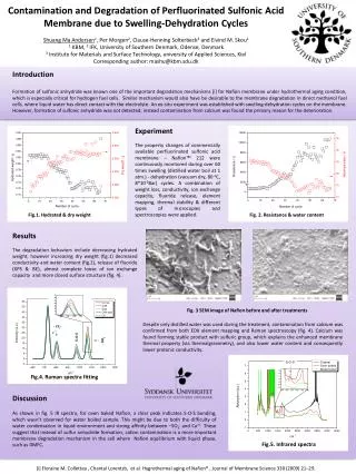
Experiment Rotating speed 1750 rpm, and power 2.5 kW
The structure of a simple transmission is shown in previous slide. If the power transfer to lay shaft is 2.5kW at 1750 rpm. The gear and the pinion is made by a material of allowable bending strength 650 Mpa, the allowable contact strength is 1200MPa. If the two reduction ratio 0.75 and 0.5 are required, please select the proper pinion and gear for this system.