Download
1 / 39
440 likes | 820 Views
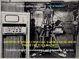
Chapter 7: Current Measurements A: Eulerian techniques/instruments 1. Mechanical current meters. “Unidirectional” (Savonius) rotor plus vane problem: Counting revolutions (giving average scalar SPEED) plus a single direction reading gives nonsense results in oscillating flows.

E N D
Chapter 7: Current Measurements A: Eulerian techniques/instruments 1. Mechanical current meters “Unidirectional” (Savonius) rotor plus vane problem: Counting revolutions (giving average scalar SPEED) plus a single direction reading gives nonsense results in oscillating flows. This was done in early Aandeeraa RCM 4/5 units. OK if no oscillating flows (no waves, mooring motion, turbulence, etc)
Vector averaging: Measure u,v rapidly (e.g. from frequent speed and direction readings), convert to earth coordinates (N/S, E/W), and average in THOSE components. RCM 7/8 can do this A BIT (but whole instrument needs to turn, and read not very often because high compass current draw). Better VACM with vanes that respond very fast, read every few seconds and 5cm of displacement.
Vertical mooring motion: If rotor does NOT respond with cos βbehaviour, e.g. measures an amplitde closer to s, then it will always read wrong (usually too large) current in up/down oscillations. U (true current) β s (total SPEED seen at rotor) but we want U=|s| cos β w (mooring motion) Normal rotors do NOT have cos β response VMCM
Additional problems: • Startup friction, or stalling in low currents, usually needs 1cm/s (once turning, accuracy can be much better) • growth/fouling: change in shape/drag calibration wrong • measuring in own wake in oscillating flows • compass problems (especially deviation by own housing, batteries, mounting, wire, ship, CTD rosette, etc…)
Different current meters in oscillating flow RCM 4/5 VACM VMCM Error/mean ACM
A: Eulerian techniques/instruments 2. Acoustic current meters
Acoustic current meter (3D-ACM) by FSI Acoustic traveltime measurement within the small volume often used for small-scale and turbulence measurements.
Modern “point” current meters (doppler measurement) All except Aanderaa can be clamped on wire and have inductive telemetry option Sontek Argonaut Nortek Aquadopp Aanderaa RDI DVS Seaguard RCM
Special Nortek quote: -------------------- $12,000 bare $1000 clamp and fin $2500 inductive modem 5% quantity discount (10) Total cost $14,400
The transducers see the following velocity projections along their beams ubeamE= -u sin φubeamW= +u sin φ wbeamE= w cos φ wbeamW= w cos φ TOTAL for each transducer: sbeamE= ubeamE+ wbeamE sbeamW= ubeamW+ wbeamW Sum and difference: u=(sbeamW-sbeamE)/2 sin φ wE_W=(sbeamE+sbeamW)/2 cos φ Same for N-S beams. The 2 estimates for w are averaged for <w> and differenced for “error velocity” – measure for quality of data/validity of assumptions…
Broadband ADCP uses coded pulses within a ping, and analyzes time/phase shift (via correlation techniques) to determine the distance/speed of moving scatterers. This gives an ambiguity if particles have travelled more than a wavelength, so in high currents only short-spaced pulses can be transmitted, reducing sampling quantity and accuracy. In low currents, pulses can be spaced further ambiguity velocity
Missing part of profile near reflector/boundary: H cos φ… 6% for 20 deg transducers !!! H
Self-contained RDI ADCP’s, approx. to shown scale Workhorse Quartermaser 38-40k$ (1500m rated) Workhorse Sentinel 24-29k$ (200-6000m rated) Workhorse Longranger 52k$ (1500m rated)
ADCP setup example:Exercise with PlanADCP Accuracy is affected by: • Bin size • Ambiguity speed • Ensemble size • Broadband/Narrowband mode Resolution is affected by: • Bin size Range is affected by: • Bin size • Ambiguity • Broadband/Narrowband mode Proximity of first bin is affected by: • Blanking • bin size • ambiguity Read the RDI Broadband Primer (excellent !)…. Note battery capacity: We have up to 3 packs (1 internal, 2 external) with 300 Wh at 0 °C 470 Wh at 20 °C hidden under “hardware settings”
Convection cells in ADCP data Surface forcing and time integral of vertical velocity
Vessel-mounted ADCP (vmADCP) vessel-mounted ADCP - typically 150 or 75kHz - now 38kHz Ocean Surveyor phased array - samples up to 1000 m depth - raw data in ship coordinates - use tilt and gyro to get earth coord. - then remove ship velocity with GPS data
uship Measured: uapparent Correct for ship motion: add uship uship with small angle error uapparent error utrue uobserved utrue uobserved Serious problem with projecting ship velocity into ocean currents: Uerror=Uship sin φ≈ 5m/s sin φ e.g. Φ=2° 17cm/s error
Lowered ADCP (lADCP): vessel-mounted ADCP Single profiles use only du/dz and integrate afterwards U= ∫du/dz dz + Const where Const from displacement during cast or bottom velocity complete profile Time [hours]
current meter comparison experiment: www.whoi.edu/science/ultramoor/
A: Eulerian techniques/instruments 3. Electromagnetic current measurements B v Electric field strength (Faraday’s law) E ~ v x B Voltage (potential difference) U = ΔΦ= ∫ E ds ~ v x B More complete with return current path: E = j/σ – v x B I Electrodes
S4 A: Generate the magnetic field actively: Marsh McBirney
Earth magnetic field B: Use earth’s magnetic field Cable measurement Fixed sensor: E = Bvert x V* where V* conductivity-weightedvertical average Moving sensor: E = Bvert x (V-V*) Free-falling measure E(z)thus V(z) except barotropic offset, i.e. only shear.Or MEASURE V with float get barotropic part V*
RAFOS float with electrodes Free-falling E-M probe
Coastal Radar: Technical details • Compact Tx & Rx antennae • 360-degree view • Nominal range 50 km (other systems exist with over 100km) • 2-3 km spatial resolution • 1-hr integration time • 13 MHz carrier frequency • Measures currents in the upper metre • Measures sea state up to the saturation limit at Hs~ 7.5 m
Radial vectors from one station Full vectors from 2 stations