Download
1 / 181
1.82k likes | 2.62k Views
Current Electricity - Chapter Outline. Lesson 1: Electric Current What is an Electric Circuit? Requirements of a Circuit Electric Current Lesson 2: Electrical Resistance Journey of a Typical Electron Resistance Lesson 3: Ohm’s Law Ohm's Law Lesson 4: Electrical Power

E N D
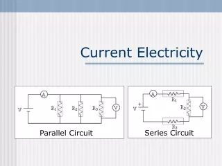
Current Electricity - Chapter Outline Lesson 1: Electric Current What is an Electric Circuit? Requirements of a Circuit Electric Current Lesson 2: Electrical Resistance Journey of a Typical Electron Resistance Lesson 3: Ohm’s Law Ohm's Law Lesson 4: Electrical Power Power: Putting Charges to Work Common Misconceptions Regarding Electric Circuits Lesson 3: Circuit Connections Circuit Symbols and Circuit Diagrams Two Types of Connections Series Circuits Parallel Circuits
Lesson 1: Electric Current - objectives • What is an Electric Circuit? • Requirements of a Circuit • Electric Current • Power: Putting Charges to Work • CommonMisconceptions Regarding Electric Circuits
What is an Electric Circuit? A circuit is simply a closed loop through which charges can continuously move.
lab: light a light bulb • you are given the following material, what arrangement would result in the successful lighting of the bulb? • Record all different ways your connection did not work. • Record all different ways your connection did work. • Write your conclusion – what you must do in order for the light bulb to work.
+ Light Bulb Anatomy • A light bulb is a device consisting of a filament attached to two wires. The wires and the filament are conducting materials which allow charge to flow through them. One wire is connected to the ribbed sides of the light bulbs. The other wire is connected to the bottom base of the light bulb. The ribbed edge and the bottom base are separated by an insulating material which prevents the direct flow of charge between the bottom base and the ribbed edge. The only pathway by which charge can make it from the ribbed edge to the bottom base or vice versa is the pathway which includes the wires and the filament.
The successful means of lighting the bulb involves placing the bottom base of the bulb on one terminal and connecting the ribbed edge to the other terminal using a wire.
The Requirement of a circuit • There must be a closed conducting loop in the external circuit which stretches from the high potential, positive terminal to the low potential, negative terminal. • There must be an energy supply capable doing work on charge to move it from a low energy location to a high energy location and thus establish an electric potential difference across the two ends of the external circuit.
example • As a + charge moves through the battery from D to A, it (gains, loses) potential energy and (gains, loses) electric potential. The point of highest energy within a battery is the (+, -) terminal. • As a + charge moves through the external circuit from A to D, it (gains, loses) potential energy and (gains, loses) electric potential. The point of highest energy within the external circuit is closest to the (+, -) terminal. • Use >, <, and = signs to compare the electric potential (V) at the four points of the circuit. VA ____ VB_______ VC _________VD
Electric Current • If the two requirements of an electric circuit are met, then charge will flow through the external circuit. This flow of charge or current, is the rate at which charge flows past a point on a circuit. Current is a rate quantity. Like velocity - the rate at which an object changes its position. Acceleration - the rate at which an object changes its velocity. And power - the rate at which work is done on an object. In every case of a rate quantity, the mathematical equation involves some quantity over time.
Electric current refers to the rate at which charge passes a given point in a circuit. Q: the amount of charge that passes a point, in Coulomb t: time, in seconds I, electric current, in ampere (A), which is a fundamental unit. 1 A = 1 C / s Current can only be sustained if there is difference inELECTRICAL POTENTIALor VOLTAGE between two points!
André-Marie Ampère (20 January 1775 – 10 June 1836) was a Frenchphysicist and mathematician who is generally regarded as one of the main discoverers of electromagnetism. The SI unit of measurement of electric current, the ampere, is named after him.
Conventional Current Direction The direction of an electric current is by convention the direction in which a positive chargewould move.
Current versus Drift Speed Current has to do with the number of coulombs of charge that pass a point in the circuit per unit of time. • Drift speed refers to the average distance traveled by a charge carrier per unit of time. Even though the drift speed is extremely slow, the current could be big. This is because there are many, many charge carriers moving at once throughout the whole length of the circuit.
The Nature of Charge Flow • We know that the average drift speed of an electron is very, very slow, why does the light in a room or in a flashlight light immediately after the switched is turned on? • Charge carriers in the wires of electric circuits are electrons. They are already there supplied by the atoms of the wire. Once the switch is turned to on, there is an electric potential difference established across the two ends of the external circuit. The electrons begin moving along a zigzag path in their usual direction. Thus, the flipping of the switch causes an immediate response throughout every part of the circuit, setting charge carriers everywhere in motion in the same net direction. • While the actual motion of charge carriers occurs with a slow speed, the signal that informs them to start moving travels at a fraction of the speed of light.
The charge carriers never become consumed or used up. While the energy possessed by the charge may be used up, the charge carriers themselves do not disintegrate, disappear or otherwise become removed from the circuit. And there is no place in the circuit where charge carriers begin to pile up or accumulate. The rate at which charge enters the external circuit on one end is the same as the rate at which charge exits the external circuit on the other end.
Check Your Understanding • A current is said to exist whenever _____. • a wire is charged • a battery is present • electric charges are unbalanced • electric charges move in a loop • Current has a direction. By convention, current is in the direction that ___. • + charges move • - electrons move • + electrons move • The drift velocity of mobile charge carriers in electric circuits is ____. • very fast; less than but very close to the speed of light • fast; faster than the fastest car but nowhere near the speed of light • slow; slower than Chris Rock runs the 200-meters • very slow; slower than a snail
Use the diagram to complete the following statements: • A current of one ampere is a flow of charge at the rate of _______ coulomb per second. • When a charge of 8 C flows past any point along a circuit in 2 seconds, the current is ________ A. • If 5 C of charge flow past point A (diagram at right) in 10 seconds, then the current is _________ A. • If the current at point D is 2.0 A, then _______ C of charge flow past point D in 10 seconds. • If 12 C of charge flow past point A in 3 seconds, then 8 C of charge will flow past point E in ________ seconds. • True or False: The current at point E is considerably less than the current at point A since charge is being used up in the light bulbs.
example • If charge flowing at the rate of 2.50 × 10¹⁶ elementary charges per second. What is the electric current?
Lesson 2: Electrical Resistance • Journey of a Typical Electron • Resistance
Resistance • Resistance is the hindrance to the flow of charge. For an electron, the journey from terminal to terminal is not a direct route. Rather, it is a zigzag path which results from countless collisions with fixed atoms within the conducting material. • While the electric potential difference established between the two terminals encourages themovement of charge, it is resistance which discourages it. • The rate at which charge flows (current) from terminal to terminal is the result of the combined affect of these two quantities: potential difference and resistance.
Variables Affecting Electrical Resistance - R • The total length of the wires will affect the amount of resistance. The longer the wire, the more resistance that there will be – R is directly proportional to length. • The cross-sectional area of the wires will affect the amount of resistance. The wider the wire, the less resistance that there will be to the flow of electric charge – R is inversely proportional to Area. • The material that a wire is made of. Some materials are better conductors than others and offer less resistance to the flow of charge. Silver is one of the best conductors but is never used in wires of household circuits due to its cost. Copper and aluminum are among the least expensive materials with suitable conducting ability to permit their use in wires of household circuits. The conducting ability of a material is resistivity. • The temperature. Since resistity increases with increasing temperature, the higher the temperature, the more resistance that there will be. You can find a list of resistivity values for various materials at temperatures of 20 degrees Celsius in your reference table.
Mathematical Nature of Resistance • The standard metric unit for resistance is the ohm, represented by the Greek letter omega - Ω . The equation representing the dependency of the resistance (R) of a cylindrically shaped conductor (e.g., a wire) upon the variables which affect it is: L represents the length of the wire (in meters), A represents the cross-sectional area of the wire (in m2), ρ represents the resistivity of the material (in Ω•meter). R represents the resistance of the wire (in Ω)
Linear R L Non Linear R A Graph of R vs. L and R vs. A • If the length of the wire is increased, Resistance is increased – direct linear relationship. • If the area of the wire is increased, Resistance is decreased – inverse relationship
example • An incandescent light bulb is supplied with a constant potential difference of 120 volts. As the filament of the bulb heats up, • What happens to the resistance? • What happens to the current?
example • Determine the resistance of a 4.00 meter length of copper wire having a diameter of 2.00 mm. Assume a temperature of 20oC.
example • What is the composition of a wire with a resistance of 31.8 Ohms if it is 5 x 10⁷ meters long and has a cross-sectional area of 0.025 m2? • What is the composition of a wire with a resistance of 31.8 Ohms if it is 5 x 10⁷ meters long and has a cross-sectional area of 0.025 m2?
example • If the cross-sectional area of a metallic conductor is halved and the length of the conductor is doubled, the resistance of the conductor will be ______________. • halved • doubled • unchanged • quadrupled
example • A 12.0-meter length of copper wire has a resistance of 1.50 ohms. How long must an aluminum wire with the same cross-sectional area be to have the same resistance?
example • Pieces of aluminum, copper, gold, and silver wire each have the same length and the same cross-sectional area. Which wire has the lowest resistance at 20°C?
Lesson 3: Ohm’s law • Ohm’s Law states the relationship between current, potential difference and resistance. “At constant temperature, the current in a metallic conductor is directly proportional to the potential difference between its ends, and inversely proportional to its resistance.” • Ohm’s Law is specific for certain materials and not general law of electricity.
V R I Ohm's Law: I = V / R • Where: V = potential in volts I = current in amperes R = resistance measured in ohms V = R∙I R = V / I I = V / R
V I Slope is resistance Resistance: R = V / I • Since R = V / I, we say that the resistance, R, is the constant of proportionality in Ohm’s law. • Resistance = ∆v / ∆I, which is the slope of a potential difference vs. current graph. The resistance is a constant for a metallic conductor at constant temperature. V I Does not obey Ohm’s Law
Ohm's Law as a Predictor of Current • This equation indicates how the two variables (potential difference and resistance) would affect the amount of current in a circuit. • The current in a circuit is directly proportional to the electric potential difference impressed across its ends and inversely proportional to the total resistance offered by the external circuit. • The greater the battery voltage (i.e., electric potential difference), the greater the current. a twofold increase in the battery voltage would lead to a twofoldincrease in the current (if all other factors are kept equal). • The greater the resistance, the less the current. An increase in the resistance of the load by a factor of two would cause the current to decrease by a factor of two to one-half its original value.
Let’s practice: I = V / R • Volts resistance current • 1.5 V 3 Ω0.50 Amp • 3.0 V 3 Ω ________ • 4.5 V 3 Ω ________ • 4.5 V 6 Ω ________ • 4.5 V 9 Ω ________ V and I have direct relationship V and I have direct relationship V and R have inverse relationship
example • The diagram below depicts a couple of circuits containing a voltage source (battery pack), a resistor (light bulb) and an ammeter (for measuring current). In which circuit does the light bulb have the greatest resistance? A B
Circuit • A path through which current flows from an area of high voltage to an area of low voltage.
Circuit Elements Voltage sources Resistances Measurement Devices Other Elements
Measurements V 100V R = 10Ω 10A 10A V V A 0V A 0V Voltmeter measures RELATIVE differences from OUTSIDE the circuit Ammeter measures flow INSIDE the circuit V = 100V V 100V
Graphs: I vs. V and I vs. R I vs. V I vs. R Slope = ∆I / ∆V = 1/R I I R V Current and potential difference have a direct relationship. The slope is equivalent to the reciprocal of the resistance of the resistor. Current and resistance have an inverse relationship
Check Your Understanding 1. Which of the following will cause the current through an electrical circuit to decrease? Choose all that apply. a. decrease the voltage b. decrease the resistance c. increase the voltage d. increase the resistance 2. A certain electrical circuit contains a battery with three cells, wires and a light bulb. Which of the following would cause the bulb to shine less brightly? Choose all that apply. a. increase the voltage of the battery (add another cell) b. decrease the voltage of the battery (remove a cell) c. decrease the resistance of the circuit d. increase the resistance of the circuit
A circuit is wired with a power supply, a resistor and an ammeter (for measuring current). The ammeter reads a current of 24 mA (milliAmps). Determine the new current if the voltage of the power supply was ... a. ... increased by a factor of 2 and the resistance was held constant. b. ... increased by a factor of 3 and the resistance was held constant. c. ... decreased by a factor of 2 and the resistance was held constant. d. ... held constant and the resistance was increased by a factor of 2. e. ... held constant and the resistance was increased by a factor of 4. f. ... held constant and the resistance was decreased by a factor of 2. g. ... increased by a factor of 2 and the resistance was increased by a factor of 2. h. ... increased by a factor of 3 and the resistance was decreased by a factor of 2. i. ... decreased by a factor of 2 and the resistance was increased by a factor of 2.
Use the Ohm's law equation to determine the missing values in the following circuits. 6 How is current controlled in A & B? 4 How is current controlled in C & D?
example • The graph shows the relationship between current and potential difference for four resistors, A, B, C, and D . Which resistor has the greatest resistance?
example • A series circuit has a total resistance of 1.00 × 10² ohms and an applied potential difference of 2.00 × 10² volts. What is the amount of charge passing any point in the circuit in 2.00 seconds?
example • A long copper wire was connected to a voltage source. The voltage was varied and the current through the wire measured, while temperature was held constant. Using the graph to find the resistance of the copper wire.
example • A student conducted an experiment to determine the resistance of a light bulb. As she applied various potential differences to the bulb, she recorded the voltages and corresponding currents and constructed the graph below. The student concluded that the resistance of the light bulb was not constant. • What evidence from the graph supports the student’s conclusion? • According to the graph, as the potential difference increased, what happens to the resistance of the light bulb?
example • A circuit consists of a resistor and a battery. Increasing the voltage of the battery while keeping the temperature of the circuit constant would result in an increase in • current, only • resistance, only • both current and resistance • neither current nor resistance
example • Sketch a graph that best represents the relationship between the potential difference across a metallic conductor and the electric current through the conductor • At constant temperature T1 • At a higher constant temperature T2. V I
Lesson 4: Electrical Power • Power: Putting Charges to Work • Common Misconceptions Regarding Electric Circuits
Power: Putting Charges to Work • Electric circuits are designed to serve a useful function. The mere movement of charge from terminal to terminal is of little use if the electrical energy possessed by the charge is not transformed into another useful form. • To equip a circuit with a battery and a wire leading from positive to negative terminal without an electrical device (light bulb, beeper, motor, etc.) would lead to a high rate of charge flow. Such a circuit is referred to as a short circuit. It would heat the wires to a high temperature and drain the battery of its energy rather quickly. • When a circuit is equipped with a light bulb, beeper, or motor, the electrical energy supplied to the charge by the battery is transformed into other forms in the electrical device. These electrical devices are generally referred to as a load.