Download
1 / 1
10 likes | 97 Views
BNL Proton Radiography and Tomography. Reduced Dose of Proton CT Compared to X-Ray CT in Tissue-Density Variation Sensitivity T. Satogata, T. Bacarian, S. Peggs, A.G. Ruggiero, and F.A. Dilmanian Brookhaven National Laboratory, Upton USA. ABSTRACT

E N D
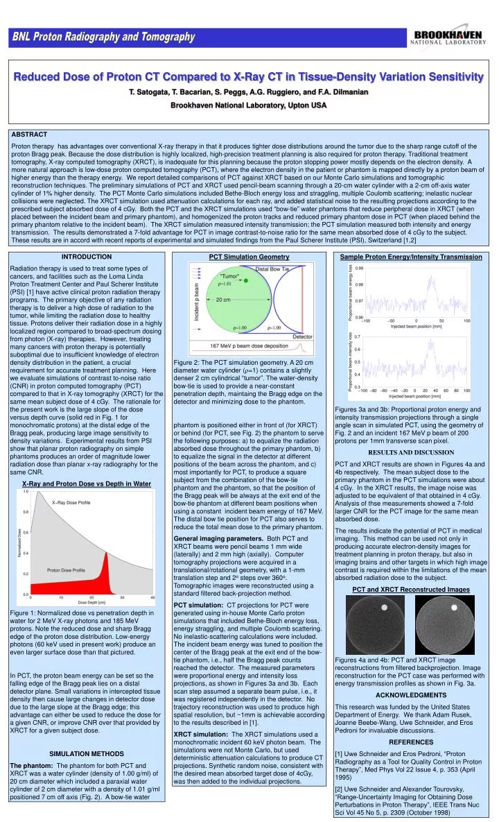
BNL Proton Radiography and Tomography Reduced Dose of Proton CT Compared to X-Ray CT in Tissue-Density Variation Sensitivity T. Satogata, T. Bacarian, S. Peggs, A.G. Ruggiero, and F.A. Dilmanian Brookhaven National Laboratory, Upton USA ABSTRACT Proton therapy has advantages over conventional X-ray therapy in that it produces tighter dose distributions around the tumor due to the sharp range cutoff of the proton Bragg peak. Because the dose distribution is highly localized, high-precision treatment planning is also required for proton therapy. Traditional treatment tomography, X-ray computed tomography (XRCT), is inadequate for this planning because the proton stopping power mostly depends on the electron density. A more natural approach is low-dose proton computed tomography (PCT), where the electron density in the patient or phantom is mapped directly by a proton beam of higher energy than the therapy energy. We report detailed comparisons of PCT against XRCT based on our Monte Carlo simulations and tomographic reconstruction techniques. The preliminary simulations of PCT and XRCT used pencil-beam scanning through a 20-cm water cylinder with a 2-cm off-axis water cylinder of 1% higher density. The PCT Monte Carlo simulations included Bethe-Bloch energy loss and straggling, multiple Coulomb scattering; inelastic nuclear collisions were neglected. The XRCT simulation used attenuation calculations for each ray, and added statistical noise to the resulting projections according to the prescribed subject absorbed dose of 4 cGy. Both the PCT and the XRCT simulations used “bow-tie” water phantoms that reduce peripheral dose in XRCT (when placed between the incident beam and primary phantom), and homogenized the proton tracks and reduced primary phantom dose in PCT (when placed behind the primary phantom relative to the incident beam). The XRCT simulation measured intensity transmission; the PCT simulation measured both intensity and energy transmission. The results demonstrated a 7-fold advantage for PCT in image contrast-to-noise ratio for the same mean absorbed dose of 4 cGy to the subject. These results are in accord with recent reports of experimental and simulated findings from the Paul Scherer Institute (PSI), Switzerland [1,2] INTRODUCTION Radiation therapy is used to treat some types of cancers, and facilities such as the Loma Linda Proton Treatment Center and Paul Scherer Institute (PSI) [1] have active clinical proton radiation therapy programs. The primary objective of any radiation therapy is to deliver a high dose of radiation to the tumor, while limiting the radiation dose to healthy tissue. Protons deliver their radiation dose in a highly localized region compared to broad-spectrum dosing from photon (X-ray) therapies. However, treating many cancers with proton therapy is potentially suboptimal due to insufficient knowledge of electron density distribution in the patient, a crucial requirement for accurate treatment planning. Here we evaluate simulations of contrast to-noise ratio (CNR) in proton computed tomography (PCT) compared to that in X-ray tomography (XRCT) for the same mean subject dose of 4 cGy. The rationale for the present work is the large slope of the dose versus depth curve (solid red in Fig. 1 for monochromatic protons) at the distal edge of the Bragg peak, producing large image sensitivity to density variations. Experimental results from PSI show that planar proton radiography on simple phantoms produces an order of magnitude lower radiation dose than planar x-ray radiography for the same CNR. X-Ray and Proton Dose vs Depth in Water Figure 1: Normalized dose vs penetration depth in water for 2 MeV X-ray photons and 185 MeV protons. Note the reduced dose and sharp Bragg edge of the proton dose distribution. Low-energy photons (60 keV used in present work) produce an even larger surface dose than that pictured. In PCT, the proton beam energy can be set so the falling edge of the Bragg peak lies on a distal detector plane. Small variations in intercepted tissue density then cause large changes in detector dose due to the large slope at the Bragg edge; this advantage can either be used to reduce the dose for a given CNR, or improve CNR over that provided by XRCT for a given subject dose. SIMULATION METHODS The phantom: The phantom for both PCT and XRCT was a water cylinder (density of 1.00 g/ml) of 20 cm diameter which included a paraxial water cylinder of 2 cm diameter with a density of 1.01 g/ml positioned 7 cm off axis (Fig. 2). A bow-tie water PCT Simulation Geometry Figure 2: The PCT simulation geometry. A 20 cm diameter water cylinder (r=1) contains a slightly denser 2 cm cylindrical “tumor”. The water-density bow-tie is used to provide a near-constant penetration depth, maintaing the Bragg edge on the detector and minimizing dose to the phantom. phantom is positioned either in front of (for XRCT) or behind (for PCT, see Fig. 2) the phantom to serve the following purposes: a) to equalize the radiation absorbed dose throughout the primary phantom, b) to equalize the signal in the detector at different positions of the beam across the phantom, and c) most importantly for PCT, to produce a square subject from the combination of the bow-tie phantom and the phantom, so that the position of the Bragg peak will be always at the exit end of the bow-tie phantom at different beam positions when using a constant incident beam energy of 167 MeV. The distal bow tie position for PCT also serves to reduce the total mean dose to the primary phantom. General imaging parameters. Both PCT and XRCT beams were pencil beams 1 mm wide (laterally) and 2 mm high (axially). Computer tomography projections were acquired in a translational/rotational geometry, with a 1-mm translation step and 2o steps over 360o. Tomographic images were reconstructed using a standard filtered back-projection method. PCT simulation: CT projections for PCT were generated using in-house Monte Carlo proton simulations that included Bethe-Bloch energy loss, energy straggling, and multiple Coulomb scattering. No inelastic-scattering calculations were included. The incident beam energy was tuned to position the center of the Bragg peak at the exit end of the bow-tie phantom, i.e., half the Bragg peak counts reached the detector. The measured parameters were proportional energy and intensity loss projections, as shown in Figures 3a and 3b. Each scan step assumed a separate beam pulse, i.e., it was registered independently in the detector. No trajectory reconstruction was used to produce high spatial resolution, but ~1mm is achievable according to the results described in [1]. XRCT simulation: The XRCT simulations used a monochromatic incident 60 keV photon beam. The simulations were not Monte Carlo, but used deterministic attenuation calculations to produce CT projections. Synthetic random noise, consistent with the desired mean absorbed target dose of 4cGy, was then added to the individual projections. Sample Proton Energy/Intensity Transmission Figures 3a and 3b: Proportional proton energy and intensity transmission projections through a single angle scan in simulated PCT, using the geometry of Fig. 2 and an incident 167 MeV p beam of 200 protons per 1mm transverse scan pixel. RESULTS AND DISCUSSION PCT and XRCT results are shown in Figures 4a and 4b respectively. The mean subject dose to the primary phantom in the PCT simulations were about 4 cGy. In the XRCT results, the image noise was adjusted to be equivalent of that obtained in 4 cGy. Analysis of thse measurements showed a 7-fold larger CNR for the PCT image for the same mean absorbed dose. The results indicate the potential of PCT in medical imaging. This method can be used not only in producing accurate electron-density images for treatment planning in proton therapy, but also in imaging brains and other targets in which high image contrast is required within the limitations of the mean absorbed radiation dose to the subject. PCT and XRCT Reconstructed Images Figures 4a and 4b: PCT and XRCT image reconstructions from filtered backprojection. Image reconstruction for the PCT case was performed with energy transmission profiles as shown in Fig. 3a. ACKNOWLEDGMENTS This research was funded by the United States Department of Energy. We thank Adam Rusek, Joanne Beebe-Wang, Uwe Schneider, and Eros Pedroni for invaluable discussions. REFERENCES [1] Uwe Schneider and Eros Pedroni, “Proton Radiography as a Tool for Quality Control in Proton Therapy”, Med Phys Vol 22 Issue 4, p. 353 (April 1995) [2] Uwe Schneider and Alexander Tourovsky, “Range-Uncertainty Imaging for Obtaining Dose Perturbations in Proton Therapy”, IEEE Trans Nuc Sci Vol 45 No 5, p. 2309 (October 1998)