Download
1 / 23
230 likes | 385 Views
L30: Partitioning. 성균관대학교 조 준 동 교수 http://vlsicad.skku.ac.kr. Partitioning in VLSI CAD. Partitioning is a technique widely used to solve diverse problems occurring in VLSI CAD. Applications of partitioning can be found in logic synthesis, logic optimization, testing, and layout synthesis.

E N D
L30: Partitioning 성균관대학교 조 준 동 교수 http://vlsicad.skku.ac.kr
Partitioning in VLSI CAD • Partitioning is a technique widely used to solve diverse problems occurring in VLSI CAD. Applications of partitioning can be found in logic synthesis, logic optimization, testing, and layout synthesis. • High-quality partitioning is critical in high-level synthesis. To be useful, high-level synthesis algorithms should be able to handle very large systems. Typically, designers partition high-level design specifications manually into procedures, each of which is then synthesized individually. However, logic decomposition of the design into procedures may not be appropriate for high-level and logic-level synthesis [60]. Different partitionings of the high-level specifications may produce substantial differences in the resulting IC chip areas and overall system performance. • Some technology mapping programs use partitioning techniques to map a circuit specified as a network of modules performing simple Boolean operations onto a network composed of specific modules available in an FPGA.
Partitioning in VLSI CAD • Since the test generation problem for large circuits may be extremely intensive computationally, circuit partitioning may provide the means to speed it up. Generally, the problem of test pattern generation is NP-complete. To date, all test generation algorithms that guarantee finding a test for a given fault exhibit the worst-case behavior requiring CPU times exponentially increasing with the circuit size. If the circuit can be partitioned into k parts (k not fixed), each of bounded size c, then the worst-case test generation time would be reduced linearly related to the circuit size. • Partitioning is often utilized in layout synthesis to produce and/or improve the placement of the circuit modules. Partitioning is used to find strongly connected subcircuits in the design, and the resulting information is utilized by some placement algorithms to place in mutual proximity components belonging to such subcircuits, thus minimizing delays and routing lengths.
Partitioning in VLSI CAD • Another important class of partitioning problems occurs at the system design level. Since IC packages can hold only a limited number of logic components and external terminals, the components must be partitioned into subcircuits small enough to be implemented in the available packages. • Partitioning has been used as well to estimate some properties of physical IC designs, such as the expected IC area.
Circuit Partitioning • The early attempts to solve the circuit partitioning problem were based on the representation of the circuit as a graph G = (V,E), where V is a set of nodes (vertices) representing the fundamental components, such as gates, flip-flops, inputs and outputs and E is a set of edges representing nets present in the network. Graph partitioning problems representing VLSI design problems usually involve separating the set of the graph nodes into disjoint subsets while optimizing some objective function defined on the graph vertices and edges. In the partitioned graph, edges can be divided into two classes: inter-subset edges whose vertices belong to different subsets, and intra-subset edges whose vertices belong to the same subset. The objective functions associated with the graph partitioning problems usually treat these classes of edges in different ways. • One classic graph partitioning problem is the minimum cut (mincut) problem. Its objective is to divide V into two disjoint parts, U and W, such that the number of the inter-subset edges is minimized. The set e(U,W) is referred to as a cut set, and the number of edges in cut set as the cut value.
Circuit Partitioning • graph and physical representation
VHDL example process communication control/data flow graph Behavioral description
Mincut Partitioning • An exact solution to the mincut problem was provided by Ford and Fulkerson [11], who transformed the mincut problem into the maximum flow (maxflow) problem. The maxflow-mincut algorithm finds a maximum flow in a network; the maxflow value is equal to the mincut value. The first heuristic algorithm for a two-way graph partitioning into equal-sized subsets was proposed by Kernighan and Lin, Their method consists of choosing an initial partition randomly and reducing the cut value by exchanging appropriately selected pairs of nodes from the subsets. After exchanging the positions, nodes are locked in new positions. In subsequent steps, pair of unlocked nodes are selected and exchanged until all nodes are locked. The execution of the algorithm stops, when it riches the local minimum. • Most nets in digital circuits are multi-point connections among more than two modules (logic gates, flip-flops, etc.). Therefore, modeling VLSI circuit partitioning problems as graph partitioning problems may lead to poor results caused by inadequate representation of multi-point nets which have to be decomposed into two-point connections. One way to approximate circuit partitioning problems is to transform the circuit into a weighted graph G' representation via a net model. For example, a multi-point net connecting n nodes may be modeled as a complete graph (clique) spanned on these nodes, i.e., containing all possible edges among these nodes.
Clustering (Cont’d) • Clustering based on criterion B below the first cut-line, then criterion A • Clustering based on criterion A below the second cut-line, then criterion B
Clustering Example • Two-cluster Partition • Three-cluster Partition
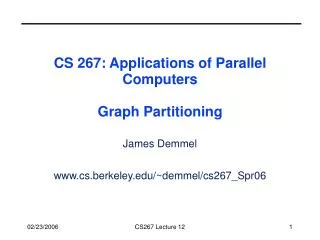
In general, computing the optimal partitioning is an NP-complete problem, which means that the best known algorithms take time which is an exponential function of n=|N| and p, and it is widely believed that no algorithm whose running time is a polynomial function of n=|N| and p exists (see ``Computers and Intractability'', M. Garey and D. Johnson, W. H. Freeman, 1979, for details.) Therefore we need to use heuristics to get approximate solutions for problems where n is large. The picture below illustrates a larger graph partitioning problem; it was generated using the spectral partitioning algorithm as implemented in the graph partitioning software by Gilbert et al, described below. The partition is N = Nblue U Nblack, with red edges connecting nodes in the two partitions. Complexity of Partitioning
Bisecting a graph G=(N,E) can be done in two ways. In the last section, we discussed finding the smallest subset Es of E such that removing Es from E divided G into two disconnected subgraphs G1 and G2, with nodes N1 and N2 respectively, where N1 U N2 = N and N1 and N2 are disjoint and equally large. (If the number of nodes is odd, we obviously cannot make |N1|=|N2|. So we will call Es an edge separator if |N1| and |N2| are sufficiently close; we will be more explicit about how different |N1| and |N2| can be only when necessary.) The edges in Es connect nodes in N1 to nodes in N2. Since removing Es disconnects G, Es is called an edge separator. The other way to bisect a graph is to find a vertex separator, a subset Ns of N, such that removing Ns and all incident edges from G also results in two disconnected subgraphs G1 and G2 of G. In other words N = N1 U Ns U N2, where all three subsets of N are disjoint, N1 and N2 are equally large, and no edges connect N1 and N2. The following figure illustrates these ideas. The green edges, Es1, form an edge separator, as well as the blue edges Es2. The red nodes, Ns, are a vertex separator, since removing them and the indicident edges (Es1, Es2, and the purple edges), leaves two disjoint subgraphs. Edge Separator and Vertex Separator Theorem. (Tarjan, Lipton, "A separator theorem for planar graphs", SIAM J. Appl. Math., 36:177-189, April 1979). Let G=(N,E) be an planar graph. Then we can find a vertex separator Ns, so that N = N1 U Ns U N2 is a disjoint partition of N, |N1| <= (2/3)*|N|, |N2| <= (2/3)*|N|, and |Ns| <= sqrt(8*|N|).
Kernighan and Lin Algorithm E(a) = external cost of a = sum[ b in B ] w(a,b) I(a) = internal cost of a = sum[ a' in A, a'!=a]w(a,a') D(a) = cost of a = E(a) - I(a) and analogously E(b) = external cost of b = sum[ a in A ] w(a,b) I(b) = internal cost of b = sum[ b' in B, b' !=b]w(b,b') D(b) = cost of b = E(b) - I(b) Then it is easy to show that swapping a in A and b in B changes T to new_T = T - ( D(a) + D(b) -2*w(a,b) ) = T - gain(a,b) In other words, gain(a,b) = D(a)+D(b)-2*w(a,b) measures the improvement in the partitioning by swapping a and b. D(a') and D(b') also change to new_D(a') = D(a') + 2*w(a',a) - 2*w(a',b) for all a' in A, a' !=a new_D(b') = D(b') + 2*w(b',b) - 2*w(b',a) for all b' in B, b' != b • B. Kernighan and S. Lin ("An effective heuristic procedure for partitioning graphs", The Bell System Technial Journal, pp. 291--308, Feb 1970), which takes O(|N|3) time per iteration. A more complicated and efficient implementation, which takes only O(|E|) time per iteration, was presented by C. Fiduccia and R. Mattheyses, "A linear-time heuristic for improving network partitions", Technical Report 82CRD130, General Electric Co., Corporate Research and Development Ceter, Schenectady, NY 1982. • We start with an edge weighted graph G=(N,E,WE), and a partitioning G = A U B into equal parts: |A| = |B|. Let w(e) = w(i,j) be the weight of edge e=(i,j), where the weight is 0 if no edge e=(i,j) exists. The goal is to find equal-sized subsets X in A and Y in B, such that exchanging X and Y reduces the total cost of edges from A to B. More precisely, we let T = sum[ a in A and b in B ] w(a,b) = cost of edges from A to B and seek X and Y such that new_A = A - X U Y and new_B = B - Y U X has a lower cost new_T. To compute new_T efficiently, we introduce:
Kernighan and Lin Algorithm ... At this point, we have computed a sequence of pairs ... (a1,b1), ... , (ak,bk) and ... gains gain(1), ..., gain(k) ... where k = |N|/2, ordered by the order in which ... we marked them (4) Pick j maximizing Gain = sumi=1...j gain(i) ... Gain is the reduction in cost from swapping ... (a1,b1),...,(aj,bj) (5) If Gain > 0 then (5.2) Update A = A - {a1,...,ak} U {b1,...,bk} ... cost = O(|N|) (5.2) Update B = B - {b1,...,bk} U {a1,...,ak} ... cost = O(|N|) (5.3) Update T = T - Gain ... cost = O(1) End if Until Gain <= 0 (0) Compute T = cost of partition N = A U B ... cost = O(|N|2) Repeat (1) Compute costs D(n) for all n in N ... cost = O(|N|2) (2) Unmark all nodes in G ... cost = O(|N|) (3) While there are unmarked nodes ... |N|/2 iterations (3.1) Find an unmarked pair (a,b) maximizing gain(a,b) ... cost = O(|N|2) (3.2) Mark a and b (but do not swap them) ... cost = O(1) (3.3) Update D(n) for all unmarked n, as though a and b had been swapped ... cost = O(|N|) End while
Spectral Partitioning • Note that there is some ambiguity in this definition, since G is undirected; writing edge e=(i,j) instead of (j,i) is equivalent to multiplying • column e of In(G) by -1. We will see that this ambiguity will not be important to us. • Definition The Laplacian matrix L(G) of G is an |N|-by-|N| symmetric matrix, with one row and column for each node. It is defined as follows. • (L(G))(i,j) = degree of node i if i=j (number of incident edges) = -1 if i!=j and there is an edge (i,j) • This is a powerful but expensive technique, based on techniques introduced by Fiedler in the 1970s, but popularized in 1990 by A. • Pothen, H. Simon, and K.-P. Liou, "Partitioning sparse matrices with eigenvectors of graphs", SIAM J. Matrix Anal. Appl., 11:430--452. We will first describe the algorithm, and then give three related justifications for its efficacy. Let G=(N,E) be an undirected, unweighted graph without self edges (i,i) or multiple edges from one node to another. We define two matrices related to this graph. • Definition The incidence matrix In(G) of G is an |N|-by-|E| matrix, with one row for each node and one column for each edge. • Suppose edge e=(i,j). Then column e of In(G) is zero except for the the i-th and j-th entries, which are +1 and -1, respectively.
Spatial Locality: Hardware Partitioning • The interface logic should be properly partitioned for area and timing reasons. Minimization of global busses leads to lower bus capacitance, and thus lower interconnect power. • Signal values within the clusters tend to be more highly correlated. • Data path should be partitioned into approximately equal size. • In the DSP area, data paths tens to occupy far more area than the control paths. • Wiring is still one of the domain area consumers • The method used to identify clusters is based on the eigenvalues and eigenvectors of the Laplacian of the graph. • The eigen vector corresponding to the second smallest eigen value provides a 1-D placement of the nodes which minimizes the mean-squared connection length.
Spectral Partitioning in VLSI placement • Setting the derivative of the Lagrangian, L, to zero gives: • The solution to the above equation are those is the eigenvalue and x is the corresponding eigenvector. • The smallest eigenvalue 0 gives a trivial solution with all nodes at the same point. The eigenvector corresponding to the second smallest eigenvalue minimizes the cost function while giving a non-trivial solution
norm(In(G)'*v)2 lambda = ------------------ norm(v)2 where norm(z)2 = sumi z(i)2 = sum{all edges e=(i,j)} (v(i)-v(j))2 ---------------------------------- sumi v(i)2 5. The eigenvalues of L(G) are nonnegative: 0 <= lambda1 <= lambda2 <= ... <= lambdan 6.The number of of connected components of G is equal to the number of lambdai) equal to 0. In particular, lambda2 != 0 if and only if G is connected. Spectral Partitioning The following theorem state some important facts about In(G) and L(G). It introduces us to the idea that the eigenvalues and eigen vectors of L(G) are related to the connectivity of G. Theorem 1. Given a graph G, its associated matrices In(G) and L(G) have the following properties. 1.L(G) is a symmetric matrix. This means the eigenvalues of L(G) are real, and its eigenvectors are real and orthogonal. 2.Let e=[1,...,1]', where ' means transpose, i.e. the column vector of all ones. Then L(G)*e = 0. 3.In(G)*(In(G))' = L(G). This is independent of the signs chosen in each column of In(G). 4.Suppose L(G)*v = lambda*v, where v is nonzero. Then
Compute the eigenvector v2 corresponding to lambda2 of L(G) for each node n of G if v2(n) < 0 put node n in partition N- else put node n in partition N+ endif endfor First we show that this partition is at least reasonable, because it tends to give connected components N- and N+: Theorem 2. (M. Fiedler, "A property of eigenvectors of nonnegative symmetric matrices and its application to graph theory", Czech.Math. J. 25:619--637, 1975.) Let G be connected, and N- and N+ be defined by the above algorithm. Then N- is connected. If no v2(n) = 0, N+ is also connected. There are a number of reasons lambda2 is called the algebraic connectivity. Here is another. Theorem 3. (Fiedler). Let G=(N,E) be a graph, and G1=(N,E1) a subgraph, i.e. with the same nodes and subset of the edges, so that G1 is "less connected" than G. Then lambda2(L(G1)) <= lambda2(L(G)), i.e. the algebraic connectivity of G1 is also less than or equal to the algebraic connectivity of G. Motivation for spectral bisection, by analogy with a vibrating string How does a taut string vibrate when it is plucked? From our background in either physics or music, we know that it has certain modes of vibration or harmonics. If we were to take snapshots of these modes, they would look like this: Spectral Partitioning