Download
1 / 26
310 likes | 515 Views
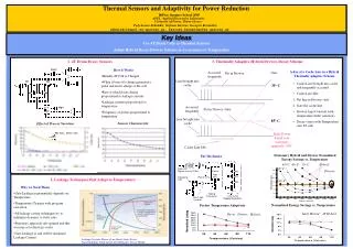
Thermal Sensors. Q = mcT , where Q is the amount of heat in J , T is temperature in K , m is the mass in kg , c is the specific heat capacity in J/( Kg.K ) , and mc is the heat capacity. Heat flows according to Where k is thermal conductivity and A is area.

E N D
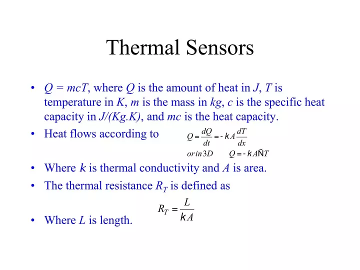
Thermal Sensors • Q = mcT, where Q is the amount of heat in J, T is temperature in K, m is the mass in kg, c is the specific heat capacity in J/(Kg.K), and mc is the heat capacity. • Heat flows according to • Where k is thermal conductivity and A is area. • The thermal resistance RT is defined as • Where L is length.
Thermal-Electrical Analogy • The best known thermal sensors are thermocouples, thermistors, thermodiodes, and thermotransistors for measuring the temperature of the environment.
Thermocouples • The Seebeck coefficient, PA, is PA = DV/DT • As a working thermocouple requires two metals, the Seebeck coefficient measured by a thermocouple, PS, is PS = PB – PA where PB is the Seebeck coefficient of the reference metal B.
Thermo-electric emf’s, DVF, and PS of various metals and alloys at 200 °C relative to platinum at 0 °C.
Mechanisms • The thermoelectric emf is associated with combined changes in the Fermi energy EF and the diffusion potential. The Fermi level effect DEF is • EF depends on temperature. • For a metal • kB is Boltzmann constant, EF(0) is EF at T = 0, and Nm(E) is the density of states in the metal. • A lowering of EF at the hot junction leads to electrons flowing towards it and thus produces a positive Seebeck coefficient.
Semiconductors often show a thermoelectric effect which is larger than that observed in metals. NC and NV are effective of states in the conduction and valence bands, respectively. n and p are the densities of free electrons and free holes, respectively. sn and sp relate to the mean free time between collisions and the charge carrier energy for electrons and holes, respectively. fn and fp take care of phonon drag for electrons and holes, respectively.
In practical situations Observed Seebeck coefficient in single-crystal Si at different dopings and temperatures.
The “figure of merit”, Z, is defined as Z for insulators, semiconductors, and metals as a function of free carrier concentration, n.
When a higher voltage output is required, a group of thermocouples can be wired in series. • The resulting structure is called a “thermopile”. A typical thermopile circuit consisting of four thermocouples.
Thermoresistors • They are based on the variation of r with T in metals. • The temperature coefficient of resistivity (TCR), ar, is • In the approximately linear region • a and b are material constants.
A 3-way compensation bridge circuit for metal thermoresistors
Semiconductor Thermoresistor: Thermistor • It is less stable and accurate than platinum thermoresistor but offers the advantages of a lower manufacturing cost and possibility of integrated interface circuitry. • The resistivity of a typical thermistor is much higher than that of a metal thermoresistor and its TCR is negative and highly non-linear • Tref is often –25 °C rather than 0 °C and b is constant
The use of intrinsic semiconductors as thermoresistors is attractive because r is governed by carrier generation mechanism rather than the mobility term. • Unfortunately, crystalline silicon does not exhibit an intrinsic behavior because the lowest impurity levels obtainable (~ 1012 cm-3) still exceed the intrinsic carrier concentration (~1010 cm-3). • Ge is used as a cryogenic temperature sensor. • Perhaps a more practical approach is to use extrinsic silicon as a thermistor.
Thermodiodes • Current voltage characteristics in a Si p/n junction diode
Energy band diagrams Reverse bias (V < 0) Forward bias (V > 0)
Variation of the forward bias current of a p/n diode with temperature
Thermotransistor • Thermotransistors offer potential benefits over other types of temperature sensors because they are more easily integrated into microelectronic circuits. • The emitter current ie in a bipolar transistor is determined by diffusion and the base-emitter voltage, Vbe, is temperature dependent. • To measure temperature using one transistor, a high collector current, ic1 is applied first followed by a second low collector current ic2. The difference in the base-emitter voltage, DVbe, now only depends upon the collector currents rather than the geometrical or material factors,
Basic temperature sensors: a n-p-n transistor in a common emitter configuration with VCE set to zero.