Download
1 / 37
560 likes | 1.53k Views
Communication Theory EE 522. Signal Space Representation and Modulation. quoted from up-dated version: P rof. Buehrer of Virginia Tech. Modulation Principles

E N D
Communication Theory EE 522 Signal Space Representation and Modulation quoted from up-dated version: Prof. Buehrer of Virginia Tech.
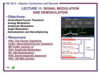
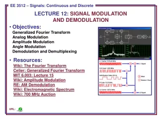
Modulation Principles • Almost all communication systems transmit digital • data using a sinusoidal carrier waveform. • Electromagnetic signals propagate well • Choice of carrier frequency allows placement of • signal in arbitrary part of spectrum • Physical system implements modulation by: • Processing digital information at baseband • Pulse shaping and filtering a digital waveform • Baseband signal is mixed with carrier signal from oscillator • RF signal is filtered, amplified and coupled with • antenna
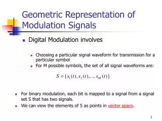
Representation of Bandpass Signals Bandpass signals (signals with small bandwidth compared to carrier frequency) can be represented in any of three standard formats: 1. Quadrature Notation s(t) = x(t) cos(2πfct) − y(t) sin(2πfct) where x(t) and y(t) are real-valued baseband signals called the in-phase and quadrature components of s(t)
(continued) • Complex Envelope Notation where is the complex baseband or envelope of . • Magnitude and Phase where is the magnitude of , and is the phase of .
Key Ideas from I/QRepresentation of Signals • We can represent bandpass signals independent of carrier frequency. • The idea of quadrature sets up a coordinate system for looking at common modulation types. • The coordinate system is sometimes called a signal constellation diagram. • Real part of complex baseband maps to x-axis and imaginary part of complex baseband maps to the y-axis
Interpretation of Signal Constellation Diagram • Axis are labeled with x(t) and y(t) • In-phase/quadrature or real/imaginary • Possible signals are plotted as points • Symbol amplitude is proportional to distance • from origin • Probability of mistaking one signal for another is • related to the distance between signal points • Decisions are made on the received signal based • on the distance of the received signal (in the I/Q plane) • to the signal points in the constellation
A New Way of Viewing Modulation • The I/Q representation of modulation is very convenient for some modulation types. • We will examine an even more general way of looking at modulation using signal spaces. • By choosing an appropriate set of axes for our signal constellation, we will be able to: • Design modulation types which have desirable properties • Construct optimal receivers for a given type of modulation • Analyze the performance of modulation types using very general techniques.
Notes on Signal Spaces Two entirely different signal sets can have the same geometric representation. The underlying geometry will determine the performance and the receiver structure for a signal set. In both of these cases we were fortunate enough to guess the correct basis functions. Is there a general method to find a complete orthonormal basis for an arbitrary signal set? Gram-Schmidt Procedure
Gram-Schmidt Procedure Suppose we are given a signal set: We would like to find a complete orthonormal basis for this signal set. The Gram-Schmidt procedure is an iterative procedure for creating an orthonormal basis.
Step 3: * No new basis function
Step 4: * No new basis function. Procedure is complete