Download
1 / 16
190 likes | 205 Views
HDL Buspro Wireless System. Last update: October 21st, 2015. Introduction.

E N D
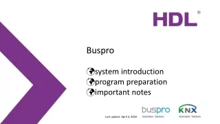
HDL Buspro Wireless System Last update: October 21st, 2015
Introduction Buspro wireless system is a mesh network system (similar to ZigBee and Z-Wave, but sure not compatible) developed and defined by HDL. HDL has also joined ZigBee Alliance and Z-Wave Alliance. We will product the device which integrated the ZigBee and Z-Wave in the future. HDL-MCIP-RF20.10 Connections: Buspro, Ethernet, Buspro wireless Work Mode: Mesh mode or Bridge mode Wireless communication distance: 50m (barrier free) Transmision power:10dBm(10mw) Installation: wall hang or table top Frequency channel: WPAN for China (780MHz – 786MHz); SRD fro Europe (864MHz – 870MHz); ISM for North America (904MHz – 928MHz) Encryption: AES HDL-MCIP-RF20.10 Wireless DLP panel
Note 1.If your building has many floors, in order to make sure the good communication, we recommend that one floor to be one independent system and set different frequency for the adjacent floors. 2.RF reliable transmission distance is 50m, obstacles will reduce the transmission distance, the distance decreases 20m if through a wall, so it is better to install in empty place and forbid to install near to the metal objects.
Working mode Mesh mode: Mesh mode features that multiple routes are available, making the network connection robust.
Working mode Bridge mode: Used to connect separated Buspro installations together, rather than using Ethernet cables. (Suppose it is inconvenient or impossible to lay Ethernet cables.)
Mesh mode In Mesh mode, the Subnet ID of all Wireless Panels and the Subnet ID of the Wireless Gateway have to be the same.
Configuration Setp steps: 1.Connect PC with Wireless Gateway via Ethernet, it has a factory default IP of 192.168.10.250 2. Change the frequency channel and password of Wireless Gateway, save. 3. Press the button of HDL-MCIP-RF20.10 three times, it will jump to wireless setup mode. 4. Set panel jump to the setup mode also. For normal wireless panel, Long press any button of it about 25s (at the 15s, the LED will flash quickly that means itenters the address modify mode), the LED will flash slowly( this mean it gets into the setup mode) For wireless DLP, select ‘WIRELESS’ on the setting page of DLP (long press the first button and last button at the same time to enter into the setting page), the seventh and eighth buttons’ LED will be on and the panel will enter the wireless setup mode. 5. Search all the wireless panels in wireless gateway and save the same frequency channel and password to all the Wireless panels. 6. Exit the setup mode. (wireless gateway and all wireless panels) 7. Wireless communication is built, HBST shall be able to search all wireless panels via the new frequency channel. Detailed user manual can be downloaded from the link, ftp://59.41.255.150/temp/to%20markeing/
Bridge mode In Bridge mode, Subnet IDs of all wireless gateways are different.
Wireless Interface We have different types for wireless power interface: HDL-MPWPID00LN.18: Fire and neutral wire for power supply HDL-MPWPID01L.18: 1CH single fire wire dimming HDL-MPWPID03L.18: 3CH single fire wire dimming HDL-MPWPID01LN.18: 1CH fire and neutral wire dimming HDL-MPWPID03LN.18: 3CH fire and neutral wire dimming HDL-MPWPIR01T.18: Fire and neutral wire for 1CH relay (with temperature detection) HDL-MPWPID01.18: Fire and neutral wire for 1CH relay
39 84 60 Wireless Interface • Power Interface with built-in 3 dimmer channels: • HDL-MPWPID03L.18 • 1st channel ≤1.2A, 2nd and 3rd channel total current≤2A. • Channel 1 is trailing edge channel, non-dimmable load or inductive transformer/ballast or fan are not allowed. Dimmable load like incandescent, LED can be connected to it. • Channel 2 and 3 are leading edge channels. • Note: the extended depth is 45mm. 84
+5V RXD TXD GND RST Wireless Interface One wireless panel can be connected with up to 4 wireless power interface, wireless panel will detect and assign channel numbers to them automatically. E.g., Power Interface module 1 be assigned with channel 1 to 3, Power Interface module 2 be assigned with channel 4 to 6, Power Interface module 3 be assigned with channel 7 to 9, Power Interface module 4 be assigned with channel 10 to 12.
Wireless Interface Loads requirements: To provide working voltage for the device, Channel 1 must be connected to the dimmable load. Recommended loads for Channel 1: Electronic transformer, LED driver etc. Inductive load is not allowed. Channel 2 and 3 are TRIAC dimming Note: Generally, if the load is lamp, the max. level should not exceed 80%. If the load is LED and less than 30W, it needs connect the constant current module in parallel to provide enough working current.