Download
1 / 21
210 likes | 415 Views
HDL coding. Synthesis vs. simulation semantics Syntax-directed translation HDL coding for synthesis. Verilog. VHDL. State machines Element structure Synthesis I/O configuration Timing model. Synthesis vs. simulation semantics. Simulation: Events are interpreted during simulation.

E N D
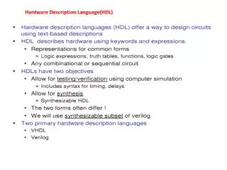
HDL coding • Synthesis vs. simulation semantics • Syntax-directed translation • HDL coding for synthesis. • Verilog. • VHDL. • State machines • Element structure • Synthesis • I/O configuration • Timing model
Synthesis vs. simulation semantics • Simulation: • Events are interpreted during simulation. • Synthesis: • Logic/memory is extracted from the description. CL
Logic synthesis • Synthesis = translation + optimization. • Translated from HDL or direct Boolean network. • Ideally, translation includes don’t-cares. • Optimization rewrites to satisfy objective functions: area, speed, power.
Syntax-directed translation x = a and b; a x b • if (a or b) • begin • x = c; • end; a b x c
Verilog simulation and synthesis • Signal assignments must use the assign keyword: • assign sig3 = sig1 & sig2;
Type name Instance name Verilog structural descriptions • Build a structure by wiring together components: input [7:0] a, b; input carryin; output [7:0] sum; output carryout; wire [7:1] carry; fulladd a0(a[0],b[0],carryin,sum[0],carry[1]); fulladd a1(a[1],b[1],carry[1],sum[1],carry[2]); fulladd a2(a[2],b[2],carry[2],sum[2],carry[3]);
VHDL for Synopsys synthesis • Each process should start with an activation list: process foo (a,b,in1,in2) • At least two processes: • combinational; • sequential. • Sequential process includes wait until clock…
Initializing variables All variables used must be initialized. Uninitialized variables cause latches to be introduced: BAD.
State machines Use case(x/z) statement to decode current state: initial begin: Init s0 = B”000”; end case (curr) 2’b00: if (in1 = ‘0’) begin o1 = a or b; end; 2’b01: ...
Process structure • How many combinational processes? • separate datapath; • single process for data and control. • Comparison: • single process is simpler; • separate datapath uses less logic. ctrl combin seq seq combin vs. dp combin
Multiplexing a datapath element case (muxctrl) 1’b0: muxout = a; 1’b1: muxout = b; end; foo = muxout or c;
Arithmetic • Can generate logic by hand. • Operators (+,-,<,>,*,+1,-1,etc.) can be mapped onto library elements. • May be limited to standard widths.
General synthesis hints • Check out all warnings carefully. • An early synthesis run keeps you from debugging a simulation that won’t synthesize.
The synthesis process • Synthesis is driven by a script: compile -map_effort med report_fpga > TOP + “.fpga” • Script may be customized for the design. • Verilog file foo.v, script file foo.script. • Typically start with a standard script.
Timing constraints • Clock period. • Duty cycle, etc. • Group path timing. • Cells or ports that share the same timing behavior. • Input/output delay. • End-to-end delay.
Hierarchical design and logic optimization • Boolean network model does not reach across component boundaries. • Tools generally won’t automatically flatten logic. • Size may blow up. • You may direct the tool to flatten a group of components. • Heuristic flattening algorithms may be used.
Instantiating memory • Use a memory model: • primitive memories based on LUT; • larger memories synthesized from multiple logic elements. • Synthesis can’t handle a memory described behaviorally. • Can handle behavioral ROM.
I/O configuration • Synthesis can automatically determine the types of many I/O blocks, configure appropriately. • Some things that need to be specified: • indirect three-state activity; • I/O pin location; • registered bidirectional I/O.
Timing model • Synthesis system reads a wire load model from a technology library. • Model depends on part, speed grade.
Attribute passing • FPGA Compiler allows attributes to be passed to EDIF: • BUFG X(.I(a),.O(b)); // synopsys attribute LOC BR
Results and reports • Save design as: • database; • EDIF. • Types of reports: • Default synthesis report. • Configuration report. • Describes LEs, IOBs, etc. • Timing report.