Download
1 / 80
810 likes | 832 Views
Introduction to Robotics. Instructed by: Iksan Bukhori. Outline. Course Information Course Overview & Objectives Course Materials Course Requirement/Evaluation/Grading (REG). I. Course Information. Instructor + Name : Arthur Silitonga + Address : Jl. Ki Hadjar Dewantara,

E N D
Introduction to Robotics Instructed by: Iksan Bukhori
Outline • Course Information • Course Overview & Objectives • Course Materials • Course Requirement/Evaluation/Grading (REG)
I. Course Information • Instructor + Name : Arthur Silitonga + Address : Jl. Ki Hadjar Dewantara, President University, Cikarang, Bekasi + Email Address : arthur@president.ac.id + Office Hours : Tuesday, 17.00 – 18.00 • Course‘s Meeting Time & Location + Meeting Time : Tuesday -> 10.30 – 13.00 (Lec) : Friday -> 07.30 – 10.00 (Lab) + Location : Room B, President University, Cikarang Baru, Bekasi
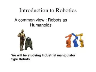
II. Course Overview & Objectives • Lecture sessions are tightly focused on introducing basic concepts of robotics from perspectives of mainly mechanics, control theory, and computer science. • Experiments at the lab occupying LEGO Mindstrom Kit, Wheeled Robot, and Robotic Atm. • Students are expected to design and implementing a real wheeled robot “from the scratch“. Course Overview
Course Objectives The objectives of this course are students should be able to : • describe positions and orientations in 3-space mathematically, and explain the geometry of mechanical manipulators generally • acquire concept of kinematics to velocities and static forces, general thought of forces & moments required to cause a motion of a manipulator, and sub-topics related to motions & mechanical designs of a manipulator • recognize methods of controlling a manipulator, and simulate the methods during lab works concerning to concepts of Wheeled Robot and Robotic Arm • design a wheeled robot “from the scratch“ based on knowledge of mechatronics To accomplish the objectives students will : • have homework assignments and participate in quizzes • implement calculations of 3-space positions & orientations using LEGO Mindstrom kit • design a wheeled robot considerating to theoretical and practical aspects • implement software aspects of a robotic arm • should take the mid-term exam, and the final exam
IV. Course Requirement/Evaluation/Grading • Requirements : - physics 1(mechanics) - linear algebra (matrix and vector) • Evaluation for the final grade will be based on : - Mid-Term Exam : 30 % - Final Exam : 30 % - Lab Experiments or Assignments : 20 % - Course Project : 20% Every two weeks, a quiz will be given as a preparation of several lab experiments
Mid-Term Exam consists of Lectures given in between the Week 1 and the Week 6. • Final Exam covers whole subjects or materials given duringthe classes. • Grading Policy Final grades may be adjusted; however, you are guaranteed the following: If your final score is 85 - 100, your grade will be A. If your final score is 70 - 84, your grade will be B. If your final score is 60 - 69, your grade will be C. If your final score is 55 - 59, your grade will beD. If your final score is < 55, your grade will be E.
REFERENCES • [Cra05]Craig, John., Introduction to Robotics : Mechanics and Control(Third Edition). Pearson Education, Inc.: New Jersey, USA. 2012. • [Sie04] Siegwart, Roland. & Nourbakhsh, Illah., Introduction to Autonomous Mobile Robots. The MIT Press : Cambridge, USA. 2004. • [Sic08]Siciliano, Bruno. & Khatib, Oussama., Handbook of Robotics. Springer-Verlag: Wuerzburg, Germany. 2008. • [Do08]Dorf, Richard. & Bishop, Robert., Modern Control Systems (Eleventh Edition). Pearson Education, Inc: Singapore, Singapore. 2008.
1. Introduction • Robotic manipulation -> parts and tools will be moved around in space by some sort of mechanism. -> leads to a need of rep. positions and orientations • Defining positions and orientations -> define coordinate systems and develop conventions for representation • Positions and orientations -> linear and rotational movement, velocities, forces, and torques
2. Description : Positions, Orientations, and Frames • Description : - tospecifyattributesofvariousobjectswithwhich a manipulationsystemdeals. - objects : parts, tools, andthemanipulatoritself.
Description of a position 1. A coordinate system has to be established. 2. Locate in the universe a point with a 3x1 position vector. AP represented as a vector and can be thought as a position in space. AP = Individual elements of a vector are given the Subscripts x, y, and z.
Figure 9.1 represents a coordinate System, {A} withthreemutually orthogonal unitvectors. Fig. 9. 1 Vector Relative to Frame
Description of an orientation • necessary to represent a point in space • important also to describe orientation of a body in space Example : A vector AP locates the point directly between the fingertips of a manipulator‘s hand, the complete location of the hand is still not specified.
In order to describe the orientation of a body, we will attach a coordinate system to the body and then give a descirption of this coordinate system relative to the reference system. Fig. 9.1 2: Locating an object in position and orientation
One way to describe the body-attached coordinate system, {B}, is to write the unit vectors of its three principal axes in terms of the coordinate system {A}. • The unit vectors giving the principal directions of coordinate system {B} as , , When written in terms of coordinate system {A}, they are called , , and
It is very convenient if we stack these three unit vectors together as the columns of a 3 x 3 matrix. • The matrix is called as a rotation matrix. Because this particular rotation matrix describes {B}relative to {A}, we name it with notation .
(2.1) (2.2) (2.3)
the description of frame {A} relative to {B} • I3 is the 3x3 identity matrix. Hence,
Description of a frame • Frame : situation of a position and an orientation • pair arises so often. • 2. Frame : a set of four vectros giving position and • orientation information. Generally, we note that a frame is a coordinate system where, in addition to the orientation, we give a position vector which locates its origin relative to some other embedding frame.
For instance : frame {B} is described by and is the vector that locates the origin of the frame {B}
There are three frames that are shown along with the universe coordinate system. Frames {A} and {B} are known relative to the universe coordinate system, and Frame {C} is known relative to Frame {A} A frame can be used as a description of one coordinate system relative to another. Fig. 2.3 Example of several frames
Positions could be represented by a frame whose rotation-matrix part is the identity matrix, and whose position-vector part locates the point being described. • An orientation could be represented by a frame whose position-vector was the zero vector.
3. Mappings : Changing Description From Frame to Frame • Mapping : changing descriptions from frame to frame. Mappings involving translated frames In Figure 2.4, we have a position by vector BP. We can express this point in space in terms of frame {A}, when {A} has the same orientation as {B}. In this case, {B} differs from {A} by a translation, which is given by , a vector that locates the origin of {B} relative to {A}. Because both vectors are defined relative to frames of the same orientation, We calculate the description of point P relative to {A}. AP, by vector addition :
In this simple example, we have illustrated mapping a vector from one frame to another. This idea of mapping, or changing the description from one frame to another, is an extremely important concept. Fig. 2.4 Translational mapping
BP is not translated, but remains the same, as instead we have computed a new description of the same point, but now with respect to system {A}. Mappings involving rotated frames We can describe an orientation by three unit vectors denoting the principal axes of a body-attached coordinate system. Indeed, stacking those three unit vectors together as the columns of a 3x3 matrix is possible.
As we have learned previously, we can describe the rotation matrix {B} relative to {A} with the notation
As depicted in Fig. 9.5, thesituation will arisewheretoknowthedefinition of a vectorwithrespecttosomeframe {B}, Wemayknowitsdefinitionwithrespecttoanotherframe, {A}, where theoriginsofthetwoframesarecoincident. Fig. 9.5 Rotating the description of a vector.
The computation is possible when a description of the orientation of {B} is known relative to {A}. • AP can be calculated as
Previous equations implement a mapping. Description of a vector, from BP, which describes a point in space relative to {B}, into AP, which is a description of the same point, but expressed relative to {A}.
Mappings involving general frames Sometimes, we have the description of a vector with respect to some frame {B}, And we would know its description with respect to another frame, {A}. The origin of frame {B} is not coincident with that of frame {A} but has a general vector offset. The vector that locates {B}‘s origin is called {B} is rotated with respect to {A}, as described by Given BP, we may computer AP.
We can first change BP to its description relative to an intermediate frame that has the same orientation as {A}, but whose origin is concident with the origin of {B}. • We then account for the translation between origins by simple vector addition, i.e.
In other words, • a “1“ is added as the öast element of the 4x1 vecttors; • a row “[0001]“ is added as the last row of the 4x4 matrix. We adopt the convention that a position vector is 3x1 or 4 x1 depending on whether it appears multiplied by a 3 x 3 matrix or by 4 x 4 matrix.
The 4 x 4 matrix is called homogeneous transform. • Just as we used rotation matrices to specify an orientation, and use of transforms to specify a frame. • Description of frame {B} relative to {A} is
4. Operators : Translations, Rotations, andTransformations • Mapping pointsbetweenframescan also beinterpretedasoperators. operators : translatepoints, rotatevectors, orboth. Translational Operators A translationmoves a point in space a finite distancealong a givenvectordirection. Understandwhichinterpretationofthemathematicsisbeingused. Example : When a vectorismoved “forward“ relative to a frame, wemay Considereitherthatvectormoved “forward“ orthattheframe Moved “backward“.
Vector AQ gives the information needed to perform the translation. The result of the operation is a new vector AP2, calculated as To write this translation operation as a matrix operator, we use the notation Fig. 9.9 Translation operator
Q is the signed magnitude of the translation along the vector direction The DQ operator may be thought as a homogenenous transform of a special simple form: Where qx, qy, and qz are the components of the translation vector Q and q =
Rotational Operators Interpretation of a rotation matrix is a rotational operator that operates on a vector AP1 and changes that vector to a new vector AP2, as a rotation, R. A rotation matrix is shown as an operator, no sub- or superscripts appear, because it is not viewed as relating two frames.
The rotation matrix that rotates vectors through some rotation, R, is the same as the rotation matrix that describes a frame rotated by R relative to the reference frame. • Another notation for a rotational operator that clearly indicates which axis is being rotated about:
RK(θ) is a rotational operator that performs a rotation about the axis direction by θ degrees. For instance, substitution into yields the operator that rotates about the axis by θ as
RK notation may be considered to represent a 3x3 or 4x4 matrix. If we define Then, the inverse of R will be Fig. 9.10 The vector AP1 rotated 30 degrees about
Transformation Operators As with vectors and rotation matrices, a frame has another interpretation as a transformation operator. In this interpretation, only one coordinate system is involved, and so the symbol T is used without sub- or superscripts. The transform that rotates by R and translates by Q is the same as the transform that describes a frame rotated by R and translated by Q relative to the reference frame.
5. Summary ofInterpretations • As a general tool to represent frames, we have introduced the homogeneous transform, a 4 x 4 matrix containing orientation and position information. • We have introduced three interpretations of this homogeneous transform:
From this point on, the terms frame and transform will both be used to refer to a position vector plus an orientation. • Frame is the term favored in speaking of a description, and transform is used most frequently when function as a mapping or operator is implied. • Note that transformations are generalizations of (and subsume) translations and rotations; we will often use the term transform when speaking of a pure rotation (or translation).
2.6 Transformation Arithmetic Compound Transformation we have CP and wish to find AP Fig. 9.12 Compoundframes : Eachisknown relative tothepreviousone
Frame {C} is known relative to frame {B}, and frame {B} is known relative to frame (A}. We can transform CP into BP as then we can transform BP into AP as we get the (not unexpected) result
Again, note that familiarity with the sub- and superscript notation makes these manipulations simple. In terms of the known descriptions of {B} and {C}, we can give the expression for as
Consider a frame {B} that is known with respect to a frame {A}—that is, we know the value of . Sometimes we will wish to invert this transform, in order to get a description of {A} relative to {B}—that is, . • A straightforward way of calculating the inverse is to compute the inverse of the 4 x 4 homogeneous transform. • However, if we do so, we are not taking full advantage of the structure inherent in the transform. • It is easy to find a computationally simpler method of computing the inverse, one that does take advantage of this structure. Inverting a Transform