Download
1 / 43
530 likes | 1.2k Views
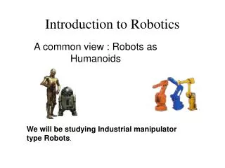
Introduction to Robotics. Robot Classes. Manipulators : robotic arms. These are most commonly found in industrial settings. Mobile Robots : unmanned vehicles capable of locomotion. Hybrid Robots : mobile robots with manipulators. (Images from AAAI and HowStuffWorks, respectively).

E N D
Robot Classes • Manipulators: robotic arms. These are most commonly found in industrial settings. • Mobile Robots: unmanned vehicles capable of locomotion. • Hybrid Robots: mobile robots with manipulators. (Images from AAAI and HowStuffWorks, respectively)
Different configuration for industrial robots: Cartesian: PPP Cylindrical: RPP Spherical: RRP SCARA: RRP (Selective Compliance Assembly Robot Arm) Articulated: RRR
Industrial robots • KUKA Robots • KAWASAKI • ABB • Fanuc • Motoman • ADEPT • Stäubli • Scara
Robot Components • Body • Effectors • Actuators • Sensors • Controller • Software
Robot::Body • Typically defined as a graph of links and joints: A link is a part, a shape with physical properties. A joint is a constraint on the spatial relations of two or more links.
Types of Joints a ball joint, which allows rotation around x, y, and z, a hinge joint, which allows rotation around z a slider joint, which allows translation along x.
Degrees of Freedom • Joints constraint free movement, measured in “Degrees of Freedom” (DOFs). • Joints reduce the number of DOFs by constraining some translations or rotations. • Robots classified by total number of DOFs
6-DOFs Robot Arm How many DOFs can you identify in your arm?
Robot::Effectors • Component to accomplish some desired physical function • Examples: • Hands • Torch • Wheels • Legs • Trumpet? (Image from http://www.toyota.co.jp/en/special/robot/)
Robot::Actuators • Actuators are the “muscles” of the robot. • These can be electric motors, hydraulic systems, pneumatic systems, or any other system that can apply forces to the system.
Robot::Controller • Controllers direct a robot how to move. • There are two controller paradigms • Open-loop controllers execute robot movement without feedback. • Closed-loop controllers execute robot movement and judge progress withsensors. They can thus compensate for errors.
Controller, Open-loop • Goal: Drive parallel to the wall. • Feedback: None. • Result: Noisy movement, due to slippage, model inaccuracy, bumps, etcetera, is likely to cause the robot to veer off the path.
Controller, Closed-loop • Goal: walk parallel to the wall. • Feedback: a proximity sensor • Result: the robot will still veer away or toward the wall, but now it can compensate.
Trajectory Error Compensation • If a robot is attempting to follow a path, it will typically veer off eventually. Controllers design to correct this error typically come in three types: • P controllers provide force in negative proportion to measured error. • PD controllers are P controllers that also add force proportional to the first derivative of measured error. • PID controllers are PD controllers that also add force proportional to the integral of measured error.
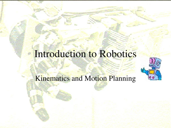
Kinematics • The calculation of position via odometry is an example of kinematics. • Kinematics is the study of motion without regard for the forces that cause it. • It refers to all time-based and geometrical properties of motion. • It ignores concepts such as torque, force, mass, energy, and inertia.
Forward Kinematics • Given the starting configuration of the mechanism and joint angles, compute the new configuration. • For a mechanism robot, this would mean calculating the position and orientation of the end effector given all the joint variables.
Kinematics of Differential Steering Derivation: X component of speed Speed is average of vr & vl Y component of speed Arc change over radius Integrate all: This is the turn radius for a circular trajectory:
Inverse Kinematics • Inverse Kinematics is the reverse of Forward Kinematics. (!) • It is the calculation of joint values given the positions, orientations, and geometries of mechanism’s parts. • It is useful for planning how to move a robot in a certain way.
Kinematics-1 of Differential Steering • Vehicles using differential steering will go in a straight line if both wheels receive the same power. • If both wheels turn at constant, but different, speeds, the vehicle follows a circular path • Distances traveled:
Transformation X=J T=J-T Xo=SX To=S-T T Object Space Joint Space Task Space =J-1X =JT T X=S-1Xo T=ST To
Kinematics Model • Forward (direct) Kinematics • Inverse Kinematics
Denavit-Hartenberg Convention • Number the joints from 1 to n starting with the base and ending with the end-effector. • Establish the base coordinate system. Establish a right-handed orthonormal coordinate system at the supporting base with axis lying along the axis of motion of joint 1. • Establish joint axis. Align the Zi with the axis of motion (rotary or sliding) of joint i+1. • Establish the origin of the ith coordinate system. Locate the origin of the ith coordinate at the intersection of the Zi & Zi-1 or at the intersection of common normal between the Zi & Zi-1 axes and the Zi axis. • Establish Xi axis. Establish or along the common normal between the Zi-1 & Zi axes when they are parallel. • Establish Yi axis. Assign to complete the right-handed coordinate system. • Find the link and joint parameters
Z3 Z1 Z0 Joint 3 X3 Z2 Y0 Y1 d2 Joint 1 X2 X0 X1 Joint 2 Y2 a0 a1 Example I • 3 Revolute Joints Link 1 Link 2
Z3 Z1 Z0 Joint 3 X3 Y0 Y1 Z2 d2 Joint 1 X0 X1 X2 Joint 2 Y2 a0 a1 Link Coordinate Frames • Assign Link Coordinate Frames: • To describe the geometry of robot motion, we assign a Cartesian coordinate frame (Oi, Xi,Yi,Zi) to each link, as follows: • establish a right-handed orthonormal coordinate frame O0 at the supporting base with Z0 lying along joint 1 motion axis. • the Ziaxis is directed along the axis of motion of joint (i + 1), that is, link (i + 1) rotates about or translates along Zi; Link 1 Link 2
Z3 Z1 Z0 Joint 3 X3 Y0 Y1 Z2 d2 Joint 1 X0 X1 X2 Joint 2 Y2 a0 a1 Link Coordinate Frames • Locate the origin of the ith coordinate at the intersection of the Zi & Zi-1 or at the intersection of common normal between the Zi & Zi-1 axes and the Zi axis. • the Xiaxis lies along the common normal from the Zi-1 axis to the Ziaxis , (if Zi-1 is parallel to Zi, then Xiis specified arbitrarily, subject only to Xibeing perpendicular to Zi);
Z3 Z1 Z0 Joint 3 X3 Y0 Y1 Z2 d2 Joint 1 X0 X1 X2 Joint 2 Y2 a0 a1 Link Coordinate Frames • Assign to complete the right-handed coordinate system. • The hand coordinate frame is specified by the geometry of the end-effector. Normally, establish Zn along the direction of Zn-1 axis and pointing away from the robot; establish Xn such that it is normal to both Zn-1 and Zn axes. Assign Yn to complete the right-handed coordinate system.
Link and Joint Parameters • Joint angle : the angle of rotation from the Xi-1 axis to the Xi axis about the Zi-1 axis. It is the joint variable if joint i is rotary. • Joint distance : the distance from the origin of the (i-1) coordinate system to the intersection of the Zi-1 axis and the Xi axis along the Zi-1 axis. It is the joint variable if joint i is prismatic. • Link length : the distance from the intersection of the Zi-1 axis and the Xi axis to the origin of the ith coordinate system along the Xi axis. • Link twist angle : the angle of rotation from the Zi-1 axis to the Zi axis about the Xi axis.
Z3 Z1 Z0 Joint 3 X3 Y0 Y1 Z2 d2 Joint 1 X0 X1 X2 Joint 2 Y2 a0 a1 Example I D-H Link Parameter Table : rotation angle from Zi-1 to Zi about Xi : distance from intersection of Zi-1 & Xi to origin of i coordinate along Xi : distance from origin of (i-1) coordinate to intersection of Zi-1 & Xi along Zi-1 : rotation angle from Xi-1to Xi about Zi-1
Example II: PUMA 260 • Number the joints • Establish base frame • Establish joint axis Zi • Locate origin, (intersect. of Zi & Zi-1) OR (intersect of common normal & Zi ) • Establish Xi,Yi t PUMA 260
J 1 -90 0 13 2 0 8 0 -l 3 90 0 4 -90 0 8 5 90 0 0 6 0 0 t Link Parameters : angle from Xi-1to Xi about Zi-1 : angle from Zi-1 to Zi about Xi : distance from intersection of Zi-1 & Xi to Oialong Xi Joint distance : distance from Oi-1 to intersection of Zi-1 & Xi along Zi-1
Transformation between i-1 and i • Four successive elementary transformations are required to relate the i-th coordinate frame to the (i-1)-th coordinate frame: • Rotate about the Z i-1 axis an angle of i to align the X i-1 axis with the X iaxis. • Translate along the Zi-1 axis a distance of di, to bring Xi-1 and Xi axes into coincidence. • Translate along the Xiaxis a distance of aito bring the two origins Oi-1 and Oi as well as the X axis into coincidence. • Rotate about the Xiaxis an angle of αi( in the right-handed sense), to bring the two coordinates into coincidence.
Basic Rotation Matrices • Rotation about x-axis with • Rotation about y-axis with • Rotation about z-axis with
Representing forward kinematics • Forward kinematics • Transformation Matrix
Review • Coordinate transformation from {B} to {A} • Homogeneous transformation matrix Rotation matrix Position vector Scaling
Transformation between i-1 and i • D-H transformation matrix for adjacent coordinate frames, i and i-1. • The position and orientation of the i-th frame coordinate can be expressed in the (i-1)th frame by the following homogeneous transformation matrix: Source coordinate Reference Coordinate
Kinematic Equations • Forward Kinematics • Given joint variables • End-effector position & orientation • Homogeneous matrix • specifies the location of the ith coordinate frame w.r.t. the base coordinate system • chain product of successive coordinate transformation matrices of Position vector Orientation matrix