Download
1 / 59
820 likes | 1.46k Views
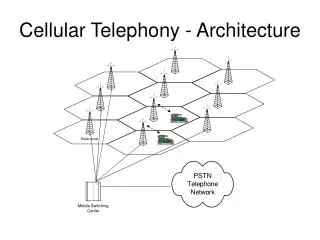
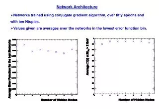
Cellular Network Architecture. Location Register (Database). Radio Network. Mobile Switching Center. Base Station Controller. MSC. Backbone Wireline Network. Mobile Terminal. Base Station. Cell. Mobility Management. Enables telecomm networks to

E N D
Cellular Network Architecture LocationRegister (Database) Radio Network Mobile Switching Center Base Station Controller MSC Backbone Wireline Network Mobile Terminal Base Station Cell
Mobility Management • Enables telecomm networks to • Locate roaming MSs for call delivery • Maintain connections as the MSs move between different cells • Involves two operations • Location Management • Handoff Management • Involves two types of mobility • Terminal mobility • Personal mobility
Types of Mobility • TERMINAL MOBILITY (Network should route calls to the MT regardless of its point of attachment) • PERSONAL MOBILITY (Users should access the network wherever they are; UPT (Universal Pers. Tel #)) • SERVICE PROVIDER MOBILITY (Allow user to roam beyond regional networks).
Mobility Management • Location Management Handoff Management Base Station A MT A is receiving a call ! How will the network deliver the call to A ?
Call Delivery (Paging) Location Update (Registration) Location Management
Too Many Location Updates Too Few Location Updates Low Paging Costs High Update Costs High Paging Costs Low Update Costs Cost Tradeoff
Solution • Local Areas (GSM) = Registration Areas (IS-41) Registration Area Boundary Center Cell
Intra-Cell Inter-Cell Hard Handoff Soft Handoff Handoff Types
AUTHENTICATION LOCATION REGISTRATION (UPDATE) DATABASE UPDATES LOCATION MANAGEMENT DATABASE QUERIES CALL DELIVERY TERMINAL PAGING Mobility Management:Location Management • Location management enables the system to track the locations of MTs between consecutive communications • Trade-off between the costs of location update and paging design optimal location management schemes to reduce the overall cost
USER MOVEMENT INITIATION NETWORK CONDITIONS RESOURCE ALLOCATION HANDOFF MANAGEMENT NEW CONNECTION GENERATION CONNECTION ROUTING BUFFERING/SEQUENCING DATA FLOW CONTROL MULTICAST Mobility Management:Handoff Management • Handoff management: an MT keeps its connection active when it moves from one access point to another one • Four types of handoffs: Network Controlled Handoff (NCHO), Mobile Controlled Handoff (MCHO), Network Assisted Handoff (NAHO), and Mobile Assisted Handoff (MAHO)
Location Management Home Location Register (HLR) BACKBONE TELEPHONE NETWORK Visitor Location Register (VLR) Mobile Switching Center MSC (MSC) VLR Mobile Terminal (MT) Local Signaling Long Distance Signaling
Location Registration MT enters a new LA, and transmits location update to new BS New LA is under same VLR. VLR updates the LA ID # for the MT. VLR determines address of HLR, and sends location registration message BS forwards update to MSC, which queries VLR HLR authenticates and registers MT by updating the VLR ID # for the MT. Then, HLR cancels former VLR. Does the MT have an existing record? Yes No
Location Registration • BS keeps broadcasting Location Area (LA) ID#. • MT listens to broadcast and will perform a location update when: • Powering up • Crossing LA boundaries • After a defined period of time
Call Delivery The MSC gives the MT a Temporary Local Directory Number, and forwards the TLDN back to the HLR Incoming call for roaming MT reaches an MSC The calling MSC determines the address of the MT’s HLR, and sends a location request message to the HLR. The HLR forwards this message to the calling MSC, which sets up a route to the MT at its current MSC. Finally, the current MSC tells all of the BSs in the MT’s LA to send a polling signal to page the MT. When the MT responds, the call is connected. The HLR sends a route request message to the VLR, which forwards the message to its MSC
How is a Cell Phone Call made? • When a mobile originates a call, a call initiation request is sent on the control channel to BS. • With this request the mobile transmits its tel number (MIN; • Mobile ID Number), electronic serial number (ESN) and tel number of the called party. • Base station receives this data and sends it to the MSC. • MSC validates the request make connection to the called party through the PSTN and instructs base station and mobile to use an idle forward and reverse voice channel to allow conversation to begin. • (in AMPS -> 10-60 voice channels; one control channel in each cell base station).
Research Areas in Location Management • Database Architectures • Paging Techniques • Multi-network location management • Location Area Design
Database Architectures • Centralized • Increase database hierarchy • Cache user locations at switching points • Replicate user profiles at more than one database • Use pointers to follow a path of VLRs to the MT’s current location • Distributed • Database Trees • Partitioning
Paging Techniques • Blanket paging • Paging the MS in all cells belonging to an LA simultaneously. • Advantage: The delay of the response to paging is kept at a minimum. • Disadvantage: Paging has to be done in several cells. • Closest-cells first • The cell where the MS was last seen is paged first followed by subsequent equidistant ring of cells. • Several rings may be polled simultaneously in a paging cycle to keep delay low. • Sequential paging • Subsequent pages are performed in most likely locations based on past history and distance.
Paging VLR (MSC)
Location Area Design • Tradeoff • Location Updates versus Terminal Paging • Goal: Improvements to tradeoff • Geographical • Fixed versus Dynamic • User-based versus Global definition • Network-specific
Dynamic Location Update Schemes • Movement-based • The MT performs an update each time it crosses a certain movement threshold, where one movement is made by crossing a cell boundary. • Distance-based • The MT performs an update when its distance from the cell where it performed its last update surpasses a certain distance threshold. • Time-based • The MT performs an update at a constant time threshold, deltaT.
Example • A MT is moving through the cellular network (R= km) as shown in the figure at a rate of 30km/hour. • Label the cell ID’s where the MT will perform its updates for: • Movement-based (T=3) • Distance-based (T=6km) • Time-based (30 minutes)
K A P F L B Q G M C R H D N S I O E J Example Figure • A MT is moving through the cellular network (R= km) at a rate of 30km/hour. • Where will updates be performed for: • Movement-based (T=3) • Distance-based (T=6km) • Time-based (30 minutes)
Answer-Movement-based K A P F L B T = 3, 2 h = 3 Update at S and G Q G M C R H D N S I O E J
Answer-Distance-based K A P F L B Q G M C T = 6, 2 h = 3 R H D N S I Update at O, and near the M/G border O E J T=6km
Answer-Time-based K A P F L B Q G M C R H D N S I Update only at M O E J
Group Problem • Design a location update and paging scheme. • Provide a diagram with numbered steps. • Explain how your scheme reduces the signaling overhead.
Handoff • The transfer of a mobile terminal’s active connection(s) from one channel to another. • Hard handoffs vs. soft handoffs • Hard handoff: break old connection, then form new connection. • Soft handoff: Connect to several BSs simultaneously. • In CDMA, handoff does not change the physical channel, it just changes the BS that handles the channel.
SIGNAL STRENGTH • Cellular systems depend on the radio signals received by an MS throughout the cell and on the contours of signal strength emanating from the BSs of two adjacent cells i and j.
Signal Strength Signal strength (in dB) Cell i Cell j -60 -60 -70 -70 -80 -80 -90 -90 -100 -100 Select cell j on right of boundary Ideal Boundary Select cell i on left of boundary
Signal Strength (2) Signal Strength (in dB) Cell j Cell i -60 -70 -60 -80 -70 -90 -80 -90 -100 -100 Signal strength contours indicating actual cell tiling. This happens because of terrain, presence of obstacles and signal attenuation in the atmosphere.
SIGNAL STRENGTH • Signal strength goes down as a mobile terminal moves away from the BS. • As the mobile terminal moves away from the BS of the cell, the signal strength weakens and the so-called HANDOFF occurs. • This implies a radio connection to another adjacent cell.
Handoff Region Signal strength due to BSj Signal strength due to BSi Pj(x) Pi(x) E Pmin BSi MS BSj X1 X3 X5 Xth X4 X2 Pz(x) (for z=1,2) denote the power received at MS from BS z. By looking at the variation of signal strength from either base station it is possible to decide on the optimum area where handoff can take place.
HANDOFF REGION • At X1 the received signal from BSj is close to 0 and the signal strength at the mobile terminal could be primarily attributed to BSi. • Similarly, at distance X2 the signal from BSi is negligible. • To receive and interpret signals correctly at mobile, the received signal must be at a minimum power level Pmin (X3 and X4), i.e., between X3 and X4 the mobile terminal can be served either by BSi or BSj.
HANDOFF REGION • The area between X3 and X4 is called HANDOFF AREA or HANDOFF REGION. • Where to perform HANDOFF depends on many factors. * Do handoff at X5 where two BSs have equal signal strength. HARD HANDOFF!!!!!
HANDOFF REGION • * Avoid “Ping-Pong Effect”, if the mobile moves back and forth between BSi and BSj * SOLUTION SOFT HANDOFF!!!!: Continue to maintain both links with BSi and BSj until the signal strength from BSj exceeds that of Bi by some pre-specified threshold value E as shown by point X in Figure.
Handoff Control • NCHO (Network-Controlled Handoff) • All close-by BSs monitor signal strength from the mobile terminal. • MSC collects data from BSs, decides best candidate BS for the mobile terminal, and initiates the MS’s handoff (CT-2, AMPS). • Results in heavy signaling load, handoff delay of many seconds. • MAHO (Mobile-Assisted Handoff) • MT monitors signal strength from nearby BSs and reports the measurements back to the BS/MSC (twice per second). • MSC decides best candidate BS and initiates the handoff (GSM) • MCHO (Mobile-Controlled Handoff) • MT monitors signal strength from nearby BSs, decides best candidate BS, and initiates handoff (DECT)
Handoff Management Radio Link Transfer (Detection & Decision) Channel Assignment
Handoff Management • Initiation (Detection/Decision) • The user, the network, or changing channel conditions detect the need for handoff. • New connection generation (Channel Assignment) • The network must find new resources for the handoff call • The network must also perform any needed routing operations. • Data flow control (Radio Link Transfer) • Delivery of the data from the old path to the new path is maintained according to agreed-upon service guarantees.
Handoff Initiation • A balance of user movement versus network conditions • Goals: • Keep user connected • Minimize network signaling • Minimize “ping-pong” handoffs
Handoff Management • Handoff in cellular telephony: • Transfer of a voice call from one BS to another • Handoff in WLANs: • Transfer of a connection from one AP (Access Point) to another • Handoff in hybrid networks: • From a BS to another, from an AP to another, from a BS to an AP, or vice versa
Handoff Decision Time Algorithms • Traditional algorithms employ thresholds • Channel measurements: • Received Signal Strength (RSS) • Measures the co-channel interference power and noise • Alternatively to RSS or in conjunction: • Path loss • Carrier-to-interference ratio (CIR) • Signal-to-interference ratio (SIR) • BER • Block error rate (BLER) • Symbol error rate (SER) • Etc.
Handoff Decision Time Algorithms • Goals: • Keep user connected • Minimize network signaling • Minimize “ping-pong” handoffs • In order to avoid the ping-pong effect, additional parameters are used such as hysteresis margin, dwell timers, and averaging windows.
Handoff Decision Time Algorithms • Received Signal Strength (RSS): The BS whose signal is received with the largest strength is selected. • RSS + Threshold: If the RSS of a new BS exceeds that of the current one and the signal strength of the current BS is below a threshold. • RSS + Hysteresis: If the RSS of a new BS is greater than that of the old BS by a hysteresis margin. • RSS + Hysteresis + Threshold: If the received signal strength of a new BS exceeds that of the current one by a hysteresis margin and the signal strength of the current BS is below a threshold. • Algorithms + Dwell Timer: A timer is started at the instant when the condition in the algorithm is true. The handoff is performed is the condition continues to be true until the timer expires.
Traditional Handoff Algorithms What kind of handoff is Happening in A, B, C, D?
Sample RSS seen by MS traveling in a straight line between them