Download
1 / 23
771 likes | 2.18k Views
Chapter 5 Directional Control Valves. Learning Objectives: The purpose of this chapter is to describe: 1. Operation of directional control valves . 2. Check valves , shuttle valves and sliding spool valves . 3. Center positions in three-position, four-way valves.

E N D
Chapter 5 Directional Control Valves Learning Objectives: The purpose of this chapter is to describe: 1. Operation of directional control valves. 2. Check valves, shuttle valves and sliding spool valves. 3. Center positions in three-position, four-way valves. 4. Applications of directional control valves. Upon completing this chapter, you should be able to: Explain the operation of the various types of directional control valves. Understand “position”, “way” and center position of a sliding spool valve.
Chapter 5 Directional Control Valves Directional control valves are designed to divert flow from one location to another or to stop it. 5.1 Check Valve A check valve allows flow in one direction, but blocks flow in the opposite direction.
Chapter 5 Directional Control Valves Because of good opposite direction seal performance the check valve is widely used in various machines Example: truk crane outrigger cylinder Problem: The cylinder cannot retract Solution: The check valve should allow opposite flow when necessary
This type of check valve always permits free in one direction but permits flow in the opposite only if pilot pressure is applied at the pilot pressure port K of the valve . When flow is directed to Port P2 and pilot pressure is enough highto exert sufficient force over the pilot piston to overcome the combined force of systematic pressure exerted on the poppet and the spring force, then reverse flow will occur.
5.2 Shuttle Valve A shuttle valve allows two alternate flow sources to be connected to one branch circuit
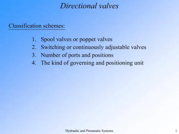
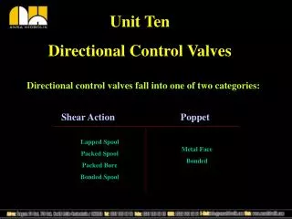
5.3 Sliding Spool Valves Most directional control valves use a sliding spool to change the path of flow through the valve. Position :For a given position of the spool, a unique flow path configuration exists within the valve. Way: The number of “ways” refers to the number of ports in the valve. Normal/Neutral/center position: The spool is not actuated
Application of 4-way, 3-position directional control valve extension iddle(brake) retraction
a. open center b. closed center c. tandem The open-center type connects all ports together. The pump flow can return directly back to the tank at essentially atmospheric pressure, little horsepower is consumed. (pump unloaded ) The actuator can be moved freely by applying an external force.(actuator floating)
a. open center b. closed center c. tandem The closed-center design has all ports blocked. The pump flow can be used for other circuit. (not unloaded) The actuator is hydraulically locked. This means it cannot be moved by the application of an external force.(actuator braking)
a. open center b. closed center c. tandem The tandem design also unloads the pump at essentially atmospheric pressure.(pump unloaded ) It also results in a locked actuator. (actuator braking)
5.4 direction Control Valve Actuation 5.4.1 Manually-actuated valve