Download
1 / 45
450 likes | 538 Views
Gamma-ray Large Area Space Telescope. DRAFT Version 3. GLAST Large Area Telescope: Instrument Design Overview Lowell A. Klaisner Stanford Linear Accelerator Center LAT Chief Engineer Klaisner@slac.stanford.edu. Overview. Gamma ray Large Area Space Telescope – GLAST

E N D
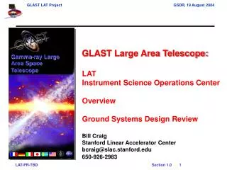
Gamma-ray Large Area Space Telescope DRAFT Version 3 GLAST Large Area Telescope: Instrument Design Overview Lowell A. Klaisner Stanford Linear Accelerator Center LAT Chief Engineer Klaisner@slac.stanford.edu
Overview • Gamma ray Large Area Space Telescope – GLAST • Large Area Telescope – LAT • LAT Subsystems • Anticoincidence Detector – ACD • Tracker – TKR • Calorimeter – CAL • Data Acquisition – DAQ • Flight Software • Mechanical Structure • LAT Thermal Design / Analysis • LAT Mechanical Design / Analysis • Manufacturing Plans • Schedule • Critical Path to Delivery of the LAT to the Spacecraft Vendor
GLAST Observatory Gamma Ray Burst Monitor (GBM) Large Area Telescope (LAT) Person Spacecraft Launch Vehicle Delta II – 2920-10H Launch Location Kennedy Space Center Orbit Altitude 575 Km Orbit Inclination 28.5 degrees Orbit Period 95 Minutes Data Ground Station Malindi, Kenya
Modular Architecture • 16 Identical Towers • Modules are Interchangeable • Redundancy at the Tower Level • Science Objectives met with failure of one Tower Tracker Calorimeter Tower Electronics Module Tower Power Supply
Instrument Structure Anti Coincidence Detector 16 Tracker Modules Grid 16 Calorimeter Modules Electronics Modules Radiators
LAT Design Changes Since January 2002 I-PDR Higher conductivity sidewalls for reduced temp gradients Full EMI shield under Grid Shorter panels clear PAF Radiators mount directly to Grid Increased separation to accommodate SC stay-clear Hole for solar array mast 6 VCHP’s per Radiator Narrower panelsfor thermal efficiency Radiators supported off Grid with Mount Brackets Slot for solar array mast Heat Pipe Patch Plate extends below Grid 4 VCHP’s per Radiator LAT Design, Jan 2002 LAT Design, July 2002
LAT Underside Design Details GASU box Empty boxes SIU boxes PDU box TPS (16x) EPU boxes TEM (16x)
Tracker Tray Structure Solid State Detectors Multi-Chip Module Wire Bonds Bias Plane Multi-Chip Module Tungsten Foil Bias Plane Solid State Detectors
Tracker Tray Configuration 18 Y Silicon Strip Detectors 18 X-Y Pairs of Planes 17 X 16 Y “Thin” Tungsten Foil (0.10 mm) 12 Locations 4 Y Tray Structure “Thick” Tungsten Foil (0.72 mm) 4 Locations 3 X 2 Y No Tungsten Foil 2 Locations 1 X 0 Y
Intrinsic LAT Measurements Characteristics • Low-level • Strip pitch: 228 mm • Plane spacing: ~3 cm • Tower size: ~60 cm tall, ~37 cm wide • Geometric characteristics: • hit resolution/plane spacing: ~2 mrad (410 arcsec) • hit resolution/tower height: 0.1 mrad (21 arcsec) • thus, on average, a tower rotation of 10 arcsec will have a very small impact on the strip hit distribution in a single event. • stack diagonal angle: 32 degrees • High-level • Photon direction determined by reconstruction software algorithms. • Different categories of events and corresponding measurement quality. • Kalman filter is used. Optimal algorithm to handle both multiple scattering and geometric effects. • At low energy, first measurements dominate due to multiple scattering. Even for cross-tower events, it is the measurements in the tower containing the conversion that dominate the direction measurement. • At high energy, it is the tower with the largest track path length that dominates the direction measurement. To good approximation, the individual tower misalignment is also the photon location misalignment. This also represents the pessimistic case.
Tracker Engineering Models • Tracker Mini-tower • Functional Model • Four Trays • Testing begun • Tracker Full Size Mechanical Tower • Thermal and Vacuum • Non-functional electronically • Verify Mechanical Model • Verify Structural Integrity
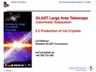
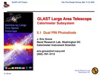
Calorimeter Module Assembly Modular Design 4 x 4 array of calorimeter modules • Each Module • 8 layers of 12 CsI(Tl) Crystals • Crystal dimensions: 27 x 20 x 326 mm • Hodoscopic stacking - alternating orthogonal layers • Dual PIN photodiode on each end of crystals. • Mechanical packaging – Carbon Composite cell structure • Electronics boards attached to each side. • Electronic readout to connectors at base of calorimeter. • Outer wall is EMI shield and provides structural stiffness as well.
Calorimeter Engineering Models • Engineering Model • Full functional and environmental testing • Structural Model • Verify new composite structure tooling and fabrication • Mass models for CDEs • Structural Flight Model • Verify composite using the autoclave and processes that will be used for flight models
Data Acquisition Boxes Layout All TEM/TPS Positions w/o an Electronic Module have EMPTY Boxes mounted to them. EPU PDU EPU GASU EPU SIU 1 SIU 2 +X +Y +Z
Instrument Flight Software System Startup Interfaces S/C Commanding LAT Control Functions Functional Requirements Thermal Authentication Housekeeping 1553 Processor Boot Real Time Commands Low Rate Science Solid State Recorder Instrument Startup Mode Control Timed Command Scripts CPU Reset Configuration Control Calibration PPS Interrupt Event Driven Commands Diagnostics GBM Interrupt GPS Message Fault Handling Attitude Message Identify Transients Watchdog Save Audit Trail Off CPU Timers GBM Message Event Monitoring EEProm / File Transient Alert Event Filtering S/C Repointing Request DAQ I/O Note: — This is instrument flight software, not spacecraft flight software — All instrument flight software is updatable during operations File Upload File Download Save Audit Trail
Event Processing Unit (1 of n) Spacecraft Interface Unit 1553 Service Baseline Architecture DAQ Front End Electronics Spacecraft Discrete Signals Command Control Configuration 1553 Command Control Configuration Calibration Calibration SIU <-> EPU CNO CNO Science SSR SIU <-> EPU Event Dispatch Event Filter SSR Service Configuration CFG/HSK/LRS Dispatch Housekeeping LRS
Instrument Flight Software System Startup Interfaces S/C Commanding LAT Control Functions Derived Functional Requirements (SIU) Thermal Authentication Housekeeping 1553 Processor Boot Real Time Commands Low Rate Science Solid State Recorder Instrument Startup Mode Control/Synch Timed Command Scripts CPU Reset Configuration Control Calibration (master) PPS Interrupt Event Driven Commands Diagnostics (master) GPS Message GBM Interrupt Fault Handling Attitude Message Identify Transients Watchdog Save Audit Trail Event Post Processing Off CPU Timers GBM Message EEProm / File Transient Alert S/C Repointing Request DAQ I/O File Upload EPU I/O File Download Save Audit Trail
Instrument Flight Software System Startup Interfaces S/C Commanding LAT Control Functions Derived Functional Requirements (EPU) Mode Control/Synch Calibration (slave) SIU I/O Processor Boot Diagnostics (slave) Event Builder I/O CPU Reset Event Monitoring Event Filtering Off CPU Timers
P C I B U S ~4 ~4 16 HSK/LRS Tower PWR Mgt HSK/LRS Tower PWR Mgt ACD Front End Electronics 1 T&DF Overall Architecture Event Processing Unit Tower Electronics Module Spacecraft Interconnect Function Event Builder C O N T R O L Tower Front End Electronics TKR TKR ASICS Processor CAL CAL ASICS CPU I/O Trigger Primitives ACD Electronics Function Global Trigger Function Spacecraft Interface Unit DAQ PWR Mgt C O N T R O L C O N T R O L HSK/LRS P C I B U S CPU I/O ACD TRG FIFO ACD ASICS LAT I/O 1553 TRG Configuration Processor SSR Spacecraft I/O Trigger Primitives Trigger Logic Discretes Key Trigger Primitives: Event Data: Configuration/Housekeeping/Low Rate Physics Data: Trigger Message: All event fragments: Command, Configuration and Control:
LAT Thermal Systems Overview MLI thermal shielding surrounding ACD, Grid Box, Electronics X-LAT Plates shunt Electronics process power to Radiators Total Max Power = 602 + 48 = 650 W Active VCHP control allows for variable Radiator area to maintain constant interface temp to LAT
LAT Thermal Systems Components • Passive thermal hardware • Radiators and X-LAT Plates • Transport and reject heat from LAT • Grid Base Assembly • Transport heat from LAT interior to Radiators • Actively-controlled hardware • Radiator VCHP’s • Heaters on reservoirs are the active feedback mechanism • Radiator anti-freeze heaters • Thermostatically-controlled to assure that VCHP’s do not freeze when LAT is in survival mode • Grid Make-up heaters • Thermostatically-controlled to make-up heat leak during survival X-LAT Plates Grid Base Assembly Radiators LAT Thermal System Components
Thermal Control System Design Lockheed-Martin Space Craft Electronics Subsystem Mechanical Subsystem Source: LAT-SS-00715-01, “LAT Thermal Control System Performance Specification ,” 23 March 2003
Structural Model • LAT structural model moved to NASTRAN • Changed FEA software from ANSYS to NASTRAN to make it more compatible with GLAST project office • Re-built model to improve dynamic analysis capabilities • Model is used to generate system structural response and interface limit loads • Subsystem models updated • New TKR model from Hytec • Updated ACD model from GSFC • Incorporated reduced CAL model from NRL • New Radiator model from LM • Re-built electronics model based on current E-Box and interface designs LAT Finite Element Model
Manufacturing Plans • ACD • Tiles Fermilab • Subassembly Goddard Space Flight Center • Tracker • Towers INFN Italy • Calorimeter • CDEs CEA France • Structure IN2P3 France • Module Assembly Naval Research Lab • DAQ • Box Level Assembly Stanford Linear Accelerator Center • Mechanical • Radiators and X-LAT Lockheed Martin • GRID Stanford Linear Accelerator Center • Integration Stanford Linear Accelerator Center
Major Design Issues • Calorimeter to Grid Interface • Achieve adequate design margins particularly in the region of the spacecraft attachment points • Cross-LAT Plate Design • Thermal interface to the Electronics Boxes • Tracker Tray Fabrication • MCM manufacturability • Honeycomb grounding • Contamination control • Manufacturing Startup • Completeness of designs • Control of material and processes