Download

1 / 61
610 likes | 613 Views
Introduction to. DVB-RCS. Presented by Sandeep Baruah Scientist ‘C’ Vigyan Prasar sandeep@vigyanprasar.gov.in. D igital V ideo B roadcasting – R eturn C hannel via S atellite. Satellite Interactive Terminal. GSAT-3.

E N D
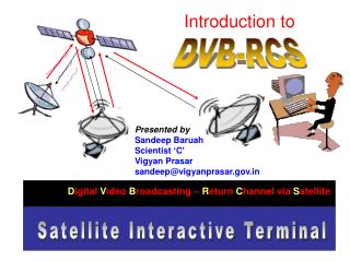
Introduction to DVB-RCS Presented by Sandeep Baruah Scientist ‘C’ Vigyan Prasar sandeep@vigyanprasar.gov.in Digital Video Broadcasting – Return Channel via Satellite Satellite Interactive Terminal
GSAT-3 DVB-RCSDigital Video Broadcasting - ReturnChannelviaSatellite aka EDUSAT
Why ‘RCviaS’? [ Return Channelvia Satellite ]? One-way multicast satellite systems are used for IPmulticast-based data, audio and video distribution. Return Channel is not required here [ This is much like a TV or radio content which offers little user interface ] and full interactivity is not possible. SIT is two-way with full user interactivity. ‘Return Channel’ is a must.
Speed of Radio Wave 300000 km /second RCS SINGLE HOPE TIME = 600 millisecond [ 0.6 second ] DOUBLE HOPE TIME = 1200 millisecond [ 1.2 second ]
Star Network SIT [ Classroom Bhubaneswar ] Star network consists of one central switch, hub or computer which acts as a router to transmit messages. Reduces chance of network failure by connecting all of the systems to a central node. This central hub rebroadcasts all transmissions received from any peripheral node to all peripheral nodes on the network, sometimes including the originating node. All peripheral nodes may thus communicate with all others by transmitting to, and receiving from, the central node only. SIT SIT Hub [ Ahmedabad ] SIT SIT [ Teaching End New Delhi ]
CLARKE ORBIT Arthur C Clarke 1945 36,000 km Non-Interactive transmissions, e.g. TV telecast
GSAT-3 aka Edusat Geostationary satellite Magic Altitude! 35,786 km The "magic" altitude of 35,786 km at which a satellite's orbital period matches, or is an integral part of, the period at which the Earth rotates: once every sidereal day (23 hours 56 minutes). In that case, the satellite is said to be geosynchronous.
Longitude 74.1439 degrees East Latitude 0.0758 degrees South Altitude 35,785.530 km Azimuth 186.5 degrees Elevation 56.4 degrees Equator Longitude 74 degrees East
Line-of-Sight Communication L O S Radio Frequencies Above 30 MHz Edusat frequencies are in the Microwave Range:11 GHz [ 11,000 MHz ] 14 GHz [ 11,000 MHz ]
Pointing the Antenna AZIMUTH ELEVATION Azimuth refers to the rotation of the whole antenna around a vertical axis. By definition North is 0 deg, East is 90 deg, South is 180 deg and west is 270 deg. North can also be called 360 deg. An approximate azimuth angle is normally sufficient. Elevation refers to the angle between the dish pointing direction, directly towards the satellite, and the local horizontal plane. It is the up-down angle.
GSAT-3 or EDUSAT is the first Indian satellite built exclusively for serving the educational sector. It is mainly intended to meet the demand for an interactive satellite based distance education system for the country, especially for the development of the population in remote and rural locations.
Though Geostationary Satellite covers a large area, it has a problem called ‘Time Lag’ [ delayed reception of signal ] Edusat users need to be aware about this constraint! Delayed reception of signal DOUBLE HOPE TIME = 1200 millisecond [ 1.2 second ] Latency Airship Satellite A theoretical alternative to satellites that is being explored is the use of ultra-light solar powered airplane or an airship [ Stratellite ] that could fly in a continuous a circling path perhaps 70,000 feet [ 20 km ] high. These would act as flying satellites, providing high-speed service to customers below the aircraft. Since the roundtrip signal distance would only be 30 miles, the latency caused by the radio wave is an almost insignificant 0.1 ms under the craft, and 2 ms at the edge of the covered area, at a 300 km (200 miles) distance.
TIME LAG - a Problem Radio Wave Travels at a speed of 3,00000 km per second 30,00000 km Suppose the radio signal has to travel a distance of 30,00000 km; it would take 10 seconds for its one way journey. To receive a reply back from the target It would take another 10 seconds. Total 20 seconds!
Single Hop calculation 1 sec [ or in 1000 millisecond ]: 300000 km 1 ms [ 0.001 sec ] : 300 km To travel 36,000: 36,000 120 ms = 300 km 120 ms 120 ms 120 ms 120 ms SIT SIT HUB 120 x 4 = 480 ms ~ as high as 600 ms
Latency: A Major Challenge in digital communication Satellite communications present one major challenge with respect to the performance of Internet applications -- the communication latency between two earth stations connected by a satellite. For GEO satellite communications systems, the latency is at least 250 milliseconds [sometimes framing, queuing, and on-board switching can add extra delays, making the end-to-end latency as high as 400 milliseconds]. This is approximately 10 times higher than a point-to-point fiber optics connection. The latency might not affect bulk data transfer and broadcast-type applications, but it will hurt highly interactive applications that require extensive handshaking between two sites. Unfortunately, one of the major Internet transport protocols, TCP, requires such interaction.
Different frequencies have different propagation characteristics MICROWAVE 1-300 GHz HF 3-30 MHz
MICROWAVES Wavelengths approximately: 30 cm [ frequency = 1 GHz ] to 1 mm [ 300 GHz ] Frequencies between 3000 MHz [ 3×10⁸ Hz ] and 300 GHz [ 3×10¹¹ Hz ]
Ku band[ Edusat uses 14 & 11 GHz ] • The Ku band (pronounced"kay-yoo"; Kurtz-under band) is a portion of the electromagnetic spectrum in the microwave range of frequencies ranging from 12 to 18GHz. • Ku band is primarily used for satellite communications, particularly for satellite backhauls from remote locations
Why Ku Band [ 12-18 GHz ]? • High bandwidth • satellite can deliver throughput at gigabits per second rates. • Inexpensive • A satellite communications system is relatively inexpensive because there are no cable-laying costs, and one satellite covers a very large area. • Untethered communication • Users can enjoy untethered communication anywhere within the footprints of the satellite. • Simple network topology • Compared with the mesh interconnection model of the terrestrial Internet, GEO satellite networks have much simpler delivery paths. The simpler topology often results in more manageable network performance.
Bandwidth 30.75 – 31.50 MHz We get bandwidth of 750 kHz only [ 0.75 MHz ] But say if we use 13.75-14.50 MHz we 750 MHz [ 0.75 GHz ]
Why Ku Band [ 12-18 GHz ]? lower frequency bands are virtually immune to radio attenuation, but are crowded, expensive and require larger antennas.It makes sense then to explore the possibility of reliable all-weather communication using higher bands (namely Ku and Ka), which are more sensitive to attenuation but less expensive.
Limitations Ku band signals can be affected by rain attenuation. In case of TV reception, only heavy rainfalls (>100 mm/hr) will have noticeable effect for the user. Due to ‘Latency’, possibility of ‘Link Failure’.
RECEIVE ONLY SIT TWO-WAY SIT DVB-RCS VSAT Network
RADIO TV Receive only SITs are also useful ONE WAY SITS can be used for Education through Entertainment + INTERACTIVE [ TWO WAY ]
Forward Link [ FL ] The link from Hub to SIT is called Forward Link (FL) The Hub is primarily responsible for carrying Internet Protocol (IP) traffic between Satellite Interactive Terminals (SITs) & other external networks. It is also responsible for overall network management & SITs management. The IP traffic at Hub is encapsulated in to MPEG-TS in DVB format. After necessary stages for modulation, frequency conversion, amplification etc., the same traffic is uplinked for SITs. The link from Hub to SIT is called Forward Link (FL) and it uses a standard Digital Video Broadcasting (DVB) format. It allows data rate up to 45 MSPS. Presently FL is configured for 10 MSPS considering satellite resources available & total traffic expected among all the SITs. The FL is like big pipe & carries the combined traffic for all SITs. Moving Picture Experts Group or MPEG is a working group of ISO/IEC charged with the development of video and audio encoding standards MSPS – Mega Samples Per Second.
Return Link [ RL ] The IP traffic at SIT is encapsulated in to either MPEG or ATM cell. After necessary stages for modulation, frequency conversion, amplification etc., the same traffic is uplinked for Hub. The link from SIT to Hub is called Return Link (RL) and it is responsible to carry the return link traffic using Multi-Frequency Time Division Multiple Access (MF-TDMA) based on ATM or MPEG standard. Single SIT allows data rate up to 2 Mbps. Presently each SIT is configured in Hub for Maximum 624 / 512 Kbps data. The RL BW for SIT is controlled by controlling nos. of time slots. In MF-TDMA, each carrier is divided in nos. of logical time slots. The Hub assigns un-assigned time slots to particular SIT. The SIT sends the traffic (either ATM/ MPEG cell) to hub using these time slots. Asynchronous Transfer Mode (ATM)is a cell relay, Circuit switching network and data link layerprotocol which encodes data traffic into small (53 bytes; 48 bytes of data and 5 bytes of header information) fixed-sized cells. This differs from other technologies based on packet-switched networks (such as the Internet Protocol or Ethernet), in which variable sized packets (sometimes known as frames) are used. ATM is a connection-oriented technology, in which a logical connection is established between the two endpoints before the actual data exchange begins.
MPEG Moving Picture Experts Group or MPEG is a working group of ISO/IEC charged with the development of video and audio encoding standards Data Rate up to 45 MSPS [MSPS – Mega Samples Per Second. Sampling rate for analog to digital converters. ] Asynchronous Transfer Mode (ATM) is a cell relay, Circuit switching network and data link layerprotocol which encodes data traffic into small (53 bytes; 48 bytes of data and 5 bytes of header information) fixed-sized cells. This differs from other technologies based on packet-switched networks (such as the Internet Protocol or Ethernet), in which variable sized packets (sometimes known as frames) are used. ATM is a connection-oriented technology, in which a logical connection is established between the two endpoints before the actual data exchange begins. Hub FL [ Forward Link ] Class Room RL [ Return Link ] : Link from SIT to Hub 624 KBPS
TDMA [ Time Division Multiple Access ] SIT RL MPEG: 11 time slots x 56.75 KBPS data rate = 624 KBPSSIT RL ATM: 24 time slots x 16 KBPS = 384 KBPS • A kilobit per second (kbit/s or kbps or kBaud) is a unit of data transfer rate equal to 1,000 bits per second. It is sometimes mistakenly thought to mean 1,024 bits per second, using the binary meaning of the kilo- prefix, though this is incorrect. • Examples: • 56K modem — 56,000 bit/s • 128 kbit/s mp3 — 128,000 bit/s [1] • 64k ISDN — 64,000 bit/s [2] • 1536k T1 — 1,536,000 bit/s (1.536 Mbit/s) • Most digital representations of audio are measured in kbit/s: • (These values vary depending on audio data compression schemes) • 4 kbit/s – minimum necessary for recognizable speech (using special-purpose speech codecs) • 8 kbit/s – telephone quality • 32 kbit/s – MW quality • 96 kbit/s – FM quality • 192 kbit/s – Nearly CD quality for a file compressed in the MP3 format • 1,411 kbit/s – CD audio (at 16-bits for each channel and 44.1 kHz) RBDC : Rate-Based Dynamic Capacity VBDC : Volume-Based Dynamic Capacity
RL- MPEG Frame for Teaching End Traffic Time Slots: T1 to T11 Carrier Frequencies: F1 to F8 Time slots used by particular SIT in MPEG Frame At present carrier carrying the MPEG cells is divided in 11 nos. of traffic time slots. Single time slot supports 56.75 kbps data rate. Each Teaching End (TE) is configured permanently (CRA) in Hub with such 11 time slots which will support up to 624 (56.75*11) Kbps RL traffic.
RL- ATM Frame for Class Room Traffic Time Slots: T1 to T32 Carrier Frequencies: F1 to F15 Time slots used by particular SIT in ATM Frame At present carrier carrying the ATM cells is divided in 32 nos. of traffic time slots & single time slot supports 16 kbps data rate. Each Class Room (CR) is configured in Hub with request based 24 time slots. I.e. 4 RBDC & 20 VBDC. This will supports up to 384 (16*24) kbps RL traffic.
RL- Types of Time Slots Return Link [ RL ] traffic is brought to Hub with use of 4 types of time slots. The SIT can be configured with one or more types of time slots. [1] Constant Rate Assignment [ CRA ] This type of time slots is assigned by Hub when particular SIT logs ON (Switch ON). CRA provides guaranteed RL bandwidth. It is most suitable for real time traffic like Video & Voice Conferencing & other non-real time applications. Each TE is configured with this type of time slots. Log On *%#! !
RL- Types of Time Slots [2] Rate Based Dynamic Control [ RBDC ] This type of time slots is assigned by Hub when particular SIT demands/requests for allotment of time slots. RBDC provides [on demand] RL bandwidth. Hub will allot the number of time slots proportional to data rate at the LAN port of SIT. It is suitable for real time traffic like Voice Conferencing & other non-real time applications like file transfer. Each CR is configured for this type of time slots. Voice Conferencing [ Real time ] File Transfer [ Non-real time]
Return Link RL- Types of Time Slots [3] Volume Based Dynamic Control [ VBDC ] This type of time slots is assigned by Hub when particular SIT demands/requests for allotment of time slots. VBDC provides (on demand) RL bandwidth. Hub will allot the number of time slots proportional to data Volume at the LAN port of SIT. It is suitable for non-real time applications. Each CR is additionally configured for this type of time slots.
RL- Types of Time Slots [ 4 ] Free Capacity Assignment (FCA) In pool of time slots with Hub, some time slots are free. The free time slots are assigned by Hub to SIT to fulfill the requirement of data transfer. It is like bonus to SIT. It is suitable for non-real time applications.
Hub Overview The system can be divided into two segments: SIT and Hub. The SIT segment represents what is installed on the customer’s site. The Hub segment represents the equipment used by the service provider.
Hub-Sub systems The communication between SITs is always through Hub. The data transmitted from one SIT is first received by Return Link Sub system (RLSS) of Hub. The data received by RLSS is routed to Forward Link Sub System (FLSS) for re-transmission. The re- transmitted data is received by another SIT. The complete Hub consists of FLSS & RLSS. The FLSS consists of ·IP Router. ·IP Encapsulator & DVB Multiplexer ·PCR Inserter (Part of RLSS) ·L-Band DVB Modulator ·Ku-Band SSPB & Antenna
Hub-Sub systems The RLSS consists of ·Antenna & LNBC ·Multi Carrier Demodulator (MCD) Board ·Signaling (SIG) Board ·Traffic (TRF) Board ·Operation, Administration and Management (OAM) plus PCR Monitor Board ·DVB Demodulator (For RCR Monitoring function) ·IP Router The OAM stores the database of all-valid SITs like MAC address, IP address, configuration files including permissible Max. bandwidth, type of access etc.
SIT Overview The satellite interactive terminal (SIT) is composed of the outdoor unit (ODU), which includes the antenna and RF transceiver, and the indoor unit (IDU).
SIT ODU [ OutDoor Unit ] • Provides RF interface with the satellite • Ku-band transmit up-converted from an L-Band IDU signal • Ku-Band receive and down-converted for L-band IDU • Series 3000 IDU supports up to 2W SSPB • ODU Mainly composed of: • Reflector • SSPB (Solid State Power Block Converter) • LNB (Low Noise Block) • Feed Horn/OMT (Ortho-Mode Translator)
[ Low Noise Block Converter ] LNBC Converts Ku Band [ 10.7-12.75 GHz ] signals to L-Band [ 0.950 -2.150 GHz ] Ku-band linear-polarised LNBAs microwave satellite signals do not easily pass through walls, roofs, or even glass windows, satellite antennas are required to be outdoors, and the signal needs to be passed indoors via cables. When radio signals are sent through coaxial cables, the higher the frequency, the more losses occur in the cable per unit of length.
SIT ODU • General Safety • Danger area near Antenna • General rule: Don’t stand in front of the Antenna!
SIT Grounding • Grounding • The ODU must be grounded in strict accordance with National and Local electrical codes. • ODU copper ground wire should be connected to the local Lightning Protection System (LPS) • Where the LPS is not available proper grounding requires installation of a ground rod(s). The copper ground wire(s) from the ODU would connect to this ground system.
Interface with IDU • Interface • IDU supplies to SSPB (Tx) • 24V DC • Transmit signal 950-1450MHz • 10 MHz reference • IDU receives 950-2150 MHz Rx signal from LNBC (Rx) & supplies 18 VDC to LNBC (Rx) • LAN Port interfaces customer’s equipment.
Customer’s LAN Connection with IDU One or more Ethernet IP address based devices (called hosts) all to gather make one LAN at customer’s site. The one LAN may have many devices like PC, Server, VOIP, IP address based camera etc. When each LAN, located at geographically different site is connected all together through SIT, make one WAN. The SIT is the part of local LAN & functions to provide connectivity of Local LAN with WAN. The IDU acts as a Gateway when traffic is towards WAN. The current IP plan for SIT is as bellow. For IDU: IP Address: 172.21.X.1 Subnet Mask: 255.255.255.0 Where X: Sequential No. assigned to each IDU.
Teaching End (Sub Hub) & Class Room (CR) Teaching End (TE)- Sub Hub All the SITs in network are physically same. Any SIT of particular user agency can be configured as a Sub Hub. The main differences in parameters configured in Hub are: For Sub Hub ·Multicast facility is enabled. ·Constant (CRA) 624 kbps (Sub Hub to Hub) RL BW is allotted for Multicast & other traffic. For Class Room (CR) ·Multicast facility is disabled & BW is of different type & less (I.e. 384 Kbps with combination of RBDC & VBDC). Additionally Sub Hub will have more facilities like servers, studio etc.
SIT Functionality Checks Let us PING ! Pinging is an integral part of SIT functionality test PING History!Mike Muuss wrote the program in December, 1983, as a tool to troubleshoot odd behavior on an IP network. He named it after the pulses of sound made by a sonar, since its operation is analogous to active sonar in submarines, in which an operator issues a pulse of energy (a network packet) at the target, which then bounces from the target and is received by the operator. Later David L. Mills provided a backronym, "Packet INternet Grouper (Groper)", also by other people "Packed INternet Gopher", after the small rodents.Michael John Muuss ( October 16 , 1958 - November 20, 2000) wrote the freeware network tool Ping. A graduate of Johns Hopkins University,he was a senior scientist at the U.S. Army Research Lab in Maryland
How to PING? RUN START TYPE CMD