Download

1 / 48
480 likes | 489 Views
AE4-S02 Spacecraft Mechatronics Displacement Sensors. Dr. ir. W. Jongkind TU-Delft 2004 – 2005. Introduction (1). Potentiometers. Linear as well as rotary potentiometer are applied. Potentiometers are used in situations where accuracy is not of major importance,

E N D
AE4-S02 Spacecraft MechatronicsDisplacement Sensors Dr. ir. W. Jongkind TU-Delft 2004 – 2005 Dr. ir. W. Jongkind AE4-S02 Spacecraft Mechatronics Displacement Sensors
Introduction (1) • Potentiometers. Linear as well as rotary potentiometer are applied. • Potentiometers are used in situations where accuracy is not of major importance, • Accuracies may vary from 0.3 % to 5 %. • Device is normally cheap. • Incremental Encoders.Linear and rotary incremental encoders are applied. • Rather inexpensive devices. • The performance depends on the resolution of the encoder slit pattern. • They can can be very accurate indeed. Dr. ir. W. Jongkind AE4-S02 Spacecraft Mechatronics Displacement Sensors
Introduction (2) • Absolute Encoders. Again linear and rotary absolute encoders exist • The code pattern is in the majority of cases a Gray code pattern, binary code patterns are much less common • Electrical Transformers • For very accurate linear displacement measurements often Linear Variable Differential Transformers (LVDT)are applied • The rotary displacement can be accurately measured with rotary electrical transformer devices such as the Resolver or Synchro Dr. ir. W. Jongkind AE4-S02 Spacecraft Mechatronics Displacement Sensors
Making the Right Choice • The following requirements and constraint should be addressed: • Required resolution • Required accuracy • Environmental constraints • Integration aspects • Availability • The selected displacement sensor is the most important factor and deciding for overall performance of a system especially when the device forms part of a feedback loop Dr. ir. W. Jongkind AE4-S02 Spacecraft Mechatronics Displacement Sensors
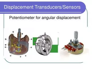
Potentiometer (1) • Operating range from 1 mm to 1m Dr. ir. W. Jongkind AE4-S02 Spacecraft Mechatronics Displacement Sensors
Potentiometer (2) Dr. ir. W. Jongkind AE4-S02 Spacecraft Mechatronics Displacement Sensors
Encoders • Typically used as shaft angle encoders • The device output is in digital form • Digital output needs in general to be transformed with the aid of a computing device to obtain magnitude and direction of movement as well as position or angle information • Consist of a pattern impressed upon a part of the system that characterizes the motion • Two main classes of optical encoders: • Absolute encoders and • Incremental encoders • For velocity measurement nearly always incremental encoders are applied Dr. ir. W. Jongkind AE4-S02 Spacecraft Mechatronics Displacement Sensors
Incremental Encoder Dr. ir. W. Jongkind AE4-S02 Spacecraft Mechatronics Displacement Sensors
Readout System Dr. ir. W. Jongkind AE4-S02 Spacecraft Mechatronics Displacement Sensors
Sense of Rotation Dr. ir. W. Jongkind AE4-S02 Spacecraft Mechatronics Displacement Sensors
Linear Encoder Codes Dr. ir. W. Jongkind AE4-S02 Spacecraft Mechatronics Displacement Sensors
Circular Encoder Codes Dr. ir. W. Jongkind AE4-S02 Spacecraft Mechatronics Displacement Sensors
Gray Encoder Output Dr. ir. W. Jongkind AE4-S02 Spacecraft Mechatronics Displacement Sensors
Encoder Construction Dr. ir. W. Jongkind AE4-S02 Spacecraft Mechatronics Displacement Sensors
Incremental Encoder Construction Dr. ir. W. Jongkind AE4-S02 Spacecraft Mechatronics Displacement Sensors
Gray EncoderConstruction Dr. ir. W. Jongkind AE4-S02 Spacecraft Mechatronics Displacement Sensors
Transformer Based Displacement Sensors • Linear Variable Differential Transformer • Synchro’s and Resolvers Dr. ir. W. Jongkind AE4-S02 Spacecraft Mechatronics Displacement Sensors
Linear Variable Differential Transformer Dr. ir. W. Jongkind AE4-S02 Spacecraft Mechatronics Displacement Sensors
Coil Voltages Dr. ir. W. Jongkind AE4-S02 Spacecraft Mechatronics Displacement Sensors
Coils in Series Opposition Dr. ir. W. Jongkind AE4-S02 Spacecraft Mechatronics Displacement Sensors
LVDT Animation Dr. ir. W. Jongkind AE4-S02 Spacecraft Mechatronics Displacement Sensors
Coil Voltages Dr. ir. W. Jongkind AE4-S02 Spacecraft Mechatronics Displacement Sensors
Amplitude versus Displacement Dr. ir. W. Jongkind AE4-S02 Spacecraft Mechatronics Displacement Sensors
Output of an LVDT • Starting at the primary or excitation side of the LVDT: Dr. ir. W. Jongkind AE4-S02 Spacecraft Mechatronics Displacement Sensors
Signal conditioning Scheme Dr. ir. W. Jongkind AE4-S02 Spacecraft Mechatronics Displacement Sensors
Signal Conditioning of a LVDT (1) • Location of the displacementtransducer coil • consider the phase of the output • as well as the magnitude • Theoutput phase of the position sensor is compared with theexcitation phase and it can be: • In or out of phase with theexcitation, depending upon which half of the coil the center ofthe armature is in Dr. ir. W. Jongkind AE4-S02 Spacecraft Mechatronics Displacement Sensors
Signal Conditioning of a LVDT (2) • This type of signal conditioning systems is available in IC form. • The Analog Devices type AD 598 IC uses this technique. Dr. ir. W. Jongkind AE4-S02 Spacecraft Mechatronics Displacement Sensors
Principle of a Resolver Dr. ir. W. Jongkind AE4-S02 Spacecraft Mechatronics Displacement Sensors
Resolver Operation Principle (1) • The rotor of the resolver is exited by an ACreference voltage of 400 Hz typically • As the rotor turns and thestator remains static an angular difference in orientation betweenrotor and stator develops: • va=Kvexitesinωtsinθ • vb=Kvexitesinωt cosθ • The shaft angle θ is obtained by first multiplying theoriginal output signals by cosφ and sinφrespectively Dr. ir. W. Jongkind AE4-S02 Spacecraft Mechatronics Displacement Sensors
Resolver Detector System Dr. ir. W. Jongkind AE4-S02 Spacecraft Mechatronics Displacement Sensors
Resolver Operation Principle (2) • Kvsinωtsinθcosφ and Kvsinωt cosθcosφ • Subtractinggives: Kvsinωt sin(θ-φ) • (θ-φ) is the angular error • Demodulated gives: A sin(θ-φ) • Signalto a phase sensitive detectorfollowed by an integrator and a Voltage Controlled Oscillator (VCO) • Detection of angle θ is based on nulling the error angle (θ-φ) Dr. ir. W. Jongkind AE4-S02 Spacecraft Mechatronics Displacement Sensors
Resolver Detector System Dr. ir. W. Jongkind AE4-S02 Spacecraft Mechatronics Displacement Sensors
Resolver Operation Principle (3) • The VCO controls an up/down counter containingthe digital equivalent of angle θ • The whole manipulation isperformed in closed loop fashion • Since the difference between θ and φ is nulled, theup/down counter supplies θ • In practice allcalculations are performed on--chip such as the AD2S90 from AnalogDevices Dr. ir. W. Jongkind AE4-S02 Spacecraft Mechatronics Displacement Sensors
Resolver Detector System Dr. ir. W. Jongkind AE4-S02 Spacecraft Mechatronics Displacement Sensors
Excitation and Read-Out Chipset Dr. ir. W. Jongkind AE4-S02 Spacecraft Mechatronics Displacement Sensors
Principle of a Synchro Dr. ir. W. Jongkind AE4-S02 Spacecraft Mechatronics Displacement Sensors
Application of Displacement Sensors (1) • Application ofLVDT's • On SOHO the LASCO experiment is flown • The device requires very accurate positioning measurement. This accurate position measurement isobtained by applying LVDT's • The LVDT's were able to measure with aresolution of 0.01 μm over a range of 30 m • An other experiment on board of SOHO, the SUMER EUVSpectrometer also applies a LVDT for linearposition measurement. This sensor has aresolution of 12 bits Dr. ir. W. Jongkind AE4-S02 Spacecraft Mechatronics Displacement Sensors
LASCO Dr. ir. W. Jongkind AE4-S02 Spacecraft Mechatronics Displacement Sensors
SOHO-LASCO Experiment Dr. ir. W. Jongkind AE4-S02 Spacecraft Mechatronics Displacement Sensors
SOHO-LASCO Experiment Dr. ir. W. Jongkind AE4-S02 Spacecraft Mechatronics Displacement Sensors
SOHO LASCO LVDT Characteristics Stroke in micrometers Dr. ir. W. Jongkind AE4-S02 Spacecraft Mechatronics Displacement Sensors
Application of Displacement Sensors (2) • Application of Resistive Encoders • The CAPS instrument on the Cassini spacecraftisequipped with a resistive encoder to measure the angular positionof the instrument Dr. ir. W. Jongkind AE4-S02 Spacecraft Mechatronics Displacement Sensors
Application of Displacement Sensors (3) • Application of Optical Encoders: • In the pointing and scanning mechanism for ATLID and SPOT5 anoptical encoder is applied to obtained angularposition. The resolution is 21 bits,its static accuracy is 15 μ rad and its bandwidth is a fewhundred Hz • For angular position measurement of a tether reel use of an incremental encoder generates 4000 pulses per revolution on two channels in quadrature. • In the scan mechanism for the Master Limb SoundingInstrument it is proposed to measure the angle ofthe elevation axis with an incremental encoder Dr. ir. W. Jongkind AE4-S02 Spacecraft Mechatronics Displacement Sensors
Application of Displacement Sensors (4) • Scanning mechanism of the MIPASInterferometer on board ENVISAT an incremental encoder isused. The outer diameter of the encoder is 182 mm containing 18000equally spaced lines. The accuracy is 1 arcsec • An 21 bits optical encoder is applied in a pointingmechanism for a Earth Observation Satellite. The resolution is 3μrad, precision over a range of 3600 is better than 15 μrad • The scan mechanism of the Atmospheric LidarInstrument makes use of an encoder • In the scanning mechanism for SPOT5a high resolutionpointing and scanning mechanism was required. The encoder applied had 21 bit resolution Dr. ir. W. Jongkind AE4-S02 Spacecraft Mechatronics Displacement Sensors
Encoder Dr. ir. W. Jongkind AE4-S02 Spacecraft Mechatronics Displacement Sensors
Application of Displacement Sensors (5) • Resolver Applications • The Infrared Atmospheric Sounder Interferometer contains the IASI instrument. Part of theinstrument is a scan sub-system for a mirror. The shaft angle ismeasured by a Resolver • The resolver assembly accuracy is 10-4 rad • The Global Ozone Scan Monitoring Experimentalso contains a resolver • Accuracy is 10 arcsec • European Robotic Arm (ERA) is equipped with a 6040 Rotasyn Dr. ir. W. Jongkind AE4-S02 Spacecraft Mechatronics Displacement Sensors
Resolver Dr. ir. W. Jongkind AE4-S02 Spacecraft Mechatronics Displacement Sensors
Rotasyn Resolver Dr. ir. W. Jongkind AE4-S02 Spacecraft Mechatronics Displacement Sensors