Download
1 / 10
100 likes | 206 Views
CAVITY LOCK ELECTRONICS. Dan Sexton, Sirish Nanda, and Abdurahim Rakhman. Design Goals. Lock-In on Cavity Resonance Slow and Fast Laser Frequency Scan Slow and Fast Error Compensation Incorporate on board micro-controller Compatible with Stanford Research SIM900 Crate. Beam Splitter.

E N D
CAVITY LOCK ELECTRONICS Dan Sexton, Sirish Nanda, and Abdurahim Rakhman
Design Goals • Lock-In on Cavity Resonance • Slow and Fast Laser Frequency Scan • Slow and Fast Error Compensation • Incorporate on board micro-controller • Compatible with Stanford Research SIM900 Crate
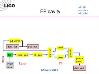
Beam Splitter Tunable Laser Cavity Oscillator PID-Regulator Photo detector Phase Shifter 0 Error signal Mixer Low Pass Filter System Schematic • Keep the cavity resonate forever • It is very hard to stabilize the cavity length in nm level Pound-Drever-Hall Locking Scheme • Detect phase of the resonance from reflected light • Feedback to tunable element to stay “locked” to resonance
Electronics Overview • Slow and Fast Laser Frequency Scan • Search for Signal of Interest • Slow Scan Rate – 0.01 Hz – 1Hz • Fast Scan Rate – 3 Hz – 30Hz • External Modulation • 10-30 mV @ 1MHz Signal • Error Input and Output • Polarity Selection (+/-)
Electronics Overview (cont’d) • Slow and Fast Error Feedback • Integration and Gain Control Loops (PI) • Gain Range – x0.1 – x1 • Integration Time – 1mS – 10mS • Optional Features • Trigger Monitor or Input • Threshold Monitor or Input
Electronics Overview (cont’d) • Analog Devices ADuC-70xx series Micro-Controller • 32-Bit 44MHz ARM processor • 8 ADC CHs and 4 DAC CHs • Drop in module in two different packages • Option A – OLIMEX Evaluation Card ADuC-7026 (3” x 3”) • Option B – OLIMEX DIP Socket ADuC-7020 (1” x 2”)
Electronics Overview (cont’d) • Stanford Research SIM900 Crate • Off the shelf “Modular System” • GPIB and RS-232 interface • Regulated Power Supply
Current Status • PCB and enclosure in hand and assembled • Bench Testing completed • In System Calibration Beginning