Download
1 / 31
310 likes | 415 Views
Electronics for the LHCb Outer Tracking Detector. Dirk Wiedner Physics Institute University of Heidelberg Germany. Tracking: Impact measurement. LHCb. CERN Switzerland. Outer Tracker. Ionising particle. 200 μ m resolution. TFC ECS. HV. L1. LV. TFC. TFC. ECS. ECS.

E N D
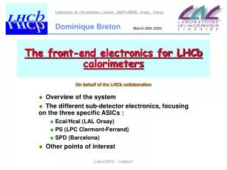
Electronics for the LHCb Outer Tracking Detector Dirk Wiedner Physics Institute University of Heidelberg Germany
Tracking: Impact measurement LHCb CERN Switzerland
Outer Tracker Ionising particle 200 μm resolution
TFC ECS HV L1 LV TFC TFC ECS ECS Power (HV,LV) Power (HV,LV) Fibers to L1 Buffer Fibers to L1 Buffer GOL LV Reg OTIS OTIS ASDBLR ASDBLR ASDBLR HV boards Fibers to L1 Buffer Fibers to L1 Buffer TFC TFC ECS ECS Power (HV,LV) Power (HV,LV) Electronics Placement tot. dose < 10krad Front end box: 128 channels 16 ASDBLR amplifiers 4 OTIS TDC chips 1 optical link: 1.6 Gbit/s Outer Tracker: 3 Stations 56000 channels 432 FE boxes = 432 optical links
Electronics Scheme Amplifier TDC optical link OTIS-TDC L0 Buffer 0-Supp. GOL DAQ (PCs) ASD ~100m 200 fC threshold Fast Control counting room FE Electronics on the detector Power / Control Electronics Service Box
GOL TDC TDC ASD ASD ASD ASD HV-Board HV-Board Electronic Components in FE-Box • GOL: Gigabit Optical Link • OTIS: Outer Tracker Time Information System • ASD : Amplifier Shaper Discriminator • HV: High Voltage x1 x4 x8 x4 432 FE-Boxes
R=1 MΩ C=330pF Z=316Ω HV-Boards • 32 channels / board • Compact capacitors • Operation in air casting/embedding of caps Capacitors: JOHANSON 302R29W331KV4E Max. Volt.: 4kV Size: 4.6 x 2 x 1.5 mm3
Casting embedding Technology Severe technological problems in the beginning: • Imperfect soldering procedure • Hand re-work Mechanical stress and damage of caps Meanwhile (several iterations) technology is well understood
56 HV boards V5*: • tested for 48 h @ 70oC, 2500V • 2 failing cap (Ileak > 100A) • 6 more boards discarded • All other caps: < 1nA / cap Satisfying result *) all channels carefully monitored during the production Production Testing Yield of 80% expected, 85 % yield reached already
ASD Board TDC • Amplifier Shaper Discriminator with Base Line Restoration • ~10 ns shaping time • 1 fC sensitivity • 8 channels • Designed for ATLAS detector • Total need of 7 200 chips • 28 896 chips available Ground springs HV Board
ASDBLR Testing Eff • Chips categorized: • pre-selection: • current consumption • broken channels etc. • →62.2% accepted • performance: • threshold spread checked • →32 % best chips chosen 0.5 Half Efficiency Vthr[50%]
OTIS TDC • 32 channel ASIC TDC • 1 ns drift time resolution • 75 ns max. drifttime • single and multi-hit • radiation tolerant • on chip L0 buffer • 2000 TDCs needed
OTIS Wafer Test not processed good • 47 wafers received 11/05 • A wafer includes: • 78 processed OTIS 1.2 • 78 processed OTIS 1.3
Test Procedure Power consumtion ok? (I<300 mA @ 2.5V) Slow control test: Check position ID and registers FPGA test: • Chip alive? • Header ok? • All channels alive? • Measurement of Differential No Linearity for ch. 0,15,16,31 • DNL < 2.0 bins* for OTIS 1.2 *) 1 bin = 0.39 ns • DNL < 1.9 bins* for OTIS 1.3 • L0 buffer overflow recognized? • DACs functional
Wafer Test on FPGA • >4 000 000 data sets per chip (7332 chips) • 1 MHz data rate (288 MBit/s) • Data analysis on FPGA • Histograms on FPGA internal memory • Drift time • Event counter • Channel map
Wafer Test Results • Overall yield: • OTIS 1.2: 88.65% →3250 functional • OTIS 1.3: 91.53% →3284 functional • ~2000 chips needed • Chips are inked and sawed
OTIS Board GOL/Aux • Chip on board technology • Cooling: • 100 μm copper plane • Noise reduction: • Air coils • Differential in and outputs ASD ASD
GOL-Auxiliary Board • GOL 1.0 serializer for 128 straw channels • QPLL 3 clock filter • TFC signal distribution • I2C signal distribution • LV-power regulators
GOL-AUX challenges • Oscillating regulators: • extra 100 μF at in and outputs • Bad clock from outside: • Radiation hard clock filter with <45 ps jitter pk-pk • Rad hard differential signal distribution: • Resistor network for current division
GOL-Aux Testing • checks: • LV ripple (<40 mV) • Fast and slow control distribution • TDC data after optical transmission • Eye pattern (optical)
Front End Tester • Test of full FE-box • Amplifier threshold characteristics • 50mV deviation exp. • Timing performance • 0.4 ns RMS typ.
Optical Link TDC L0 Buffer GOL 0-supp. DAQ ASD O-Rx ~100m 200 fC bias L0 BX counting room FE Electronics on the detector HV LV TFC ECS Cooling Power / Control Electronics Service Box
O-RxCard c o n n e c t o r 200 pin Samtec QTS-100-03 TLK 2501 TLK 2501 LED TLK 2501 TLK 2501 m o n i t o r TLK 2501 TLK 2501 SNAP12 spec. power QUARTZ c o n n e c t o r 200 pin Samtec QTS-100-03 TLK 2501 TLK 2501 c o n t r o l TLK 2501 TLK 2501 TLK 2501 TLK 2501 power O-RxCard • 12 way optical receiver • commercial deserializers • high density connector to TELL1 • 19.2 GBit/s
O-RxCard • O-RxCard now LHCb wide used • Final production carried out by Tsinghua University • All boards produced • Testing ongoing
O-RxCard BERT • Bit error rate tested vs. optical attenuation • 6 dB extra attenuation Ok • < 10 errors in 1012 Bit at 9 dB attenuation in production test
e- Test Beam Feb. 2005, DESY Hamburg electron beam 6 GeV readout silicon tracker beam scintillator +scintillator 1 2 3 4 0 1 2 3 4 5 6 7 module layer
Efficiency vs. High Voltage 1 Efficiency 0.8 0.6 0.4 0.2 0 0 0.5 1 1,5 2 2,5 3 Radius[mm] Efficiency Efficiency [%]
2,9 fC Schwelle Track resolution vs. HV Resolution [μm]
Test beam conclusion • resolution < 200 μm • Efficiency > 98% • Complete read out chain with 4 FE boxes used • Readout fully functional, performance as specified
Summary • Excellent performance of full readout electronic • All custom amplifiers and TDC produced and tested, good yield • Production of all electronic boards has started, 7% of each type of board produced and tested
C-Frames Assembly @ NIKHEF Installation @ CERN FE Production, Assembly and Test @ NIKHEF Installation @ CERN Outlook Oct nov dec jan feb mar apr may jun jul aug sep oct nov Module Finishing, S-Module Coupling etc. Ship to CERN metallic structure production Install aug sep oct nov Start LHCb global commissioning 2005 2006