Download
1 / 32
700 likes | 1.42k Views
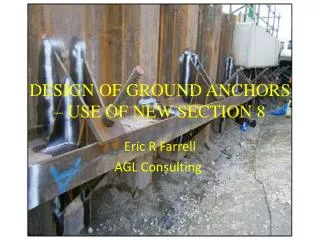
DESIGN OF GROUND ANCHORS – USE OF NEW SECTION 8. Eric R Farrell AGL Consulting . Section 8 Anchors Anchor must have a free length This presentation will cover the design of grouted anchor. ASSOCIATED STANDARDS. EN1537:2013 Execution of special geotechnical work – Ground Anchors.

E N D
DESIGN OF GROUND ANCHORS – USE OF NEW SECTION 8 Eric R Farrell AGL Consulting.
Section 8 Anchors • Anchor must have a free length • This presentation will cover the design of grouted anchor Design of Anchors – Use of New Section 8:EC 7
ASSOCIATED STANDARDS • EN1537:2013 Execution of special geotechnical work – Ground Anchors. Note – A ‘grouted anchor’ in EN1997-1 is termed a ‘ground anchor’ in EN 1537 • EN ISO 22477-5 Geotechnical investigation and testing-Testing of geotechnical structures-Part 5:Testing of pre-stressed ground anchors (only in draft form at present) Design of Anchors – Use of New Section 8:EC 7
DESIGN EXAMPLE – THE DESIGN ISSUE DESIGN ANCHOR TO SUPPORT SHEET PILED QUAY WALL Lake (water) 6m Sandy Gravel Design Approach 1 used Design is based on 3m anchor spacing. Design of Anchors – Use of New Section 8:EC 7
CONSTRUCTION STAGES Anchor prestressed at this stage 2m (with overdig) 1m Design of Anchors – Use of New Section 8:EC 7
Surcharge of 20kPa 6.5m with overdig Design of Anchors – Use of New Section 8:EC 7
FUNDAMENTAL DESIGN REQUIREMENTS The design of the anchors must consider:- • Ultimate Limit States (ULS) and Serviceability Limit States (SLS) of the anchor, • ULS and SLS of the supported structure. • Prestressforces and the effect of prestress forces, where relevant. Design of Anchors – Use of New Section 8:EC 7
Ultimate limit state (ULS) design force to be resisted by the anchors EULS,d≤ RULS;dEq. 8.1 whereEULS,d = max(FULS,d; FServ,d) Eq. 8.2 andFServ,d = gServFServ,kEq. 8.3 RULS;d = Design value of the resistance of an anchor complying with ULS criteria EULS,d = ULS design force to be resisted by the anchor FULS,d = Design value of the force required to prevent anyULS in the supported structure. FServ,d = design value of the maximum anchor force (expected within the design life of the anchor), including effect of lock off load, and sufficient to prevent a SLS in the supported structure. gServ = partial factor Design of Anchors – Use of New Section 8:EC 7
Serviceability Limit State WHERE REQUIRED IN THE NA FServ,k ≤ RSLS;dEq.8.4 FServ,k= characteristic value of the maximum anchor force (expected within the design life of the anchor), including effect of lock off load, and sufficient to prevent a SLS in the supported structure. RSLS;d= design value of the resistance of an anchor complying with SLS criteria Note, assumes partial factor of unity Design of Anchors – Use of New Section 8:EC 7
Note:- RULS;dand, where required RSLS;d must be determined/validated by anchor tests. Design of Anchors – Use of New Section 8:EC 7
Geotechnical ULS resistance of anchor = min{Rm(aULS or kl;ULS) and PP} Eq. 8.5 = Eq. 8.6 PP = Proof load RULS,mis the measured value of the resistance of an anchor complying with ULS (RULS,m)min is the lowest value of RULS;m measured from a number of investigation or suitability tests (n), for each distinct ground condition RULS;kis the characteristic value of the resistance of an anchor complying with ULS. aULS is the creep rate kl;ULSis the load loss Design of Anchors – Use of New Section 8:EC 7
Geotechnical ULS resistance of anchor continued = Eq. 8.6 RULS,dis the design value of the resistance of an anchor complying with ULS ga;ULS is a partial factor Design of Anchors – Use of New Section 8:EC 7
Geotechnical SLS resistance of anchor(where required) = min{Rm(aSLS or kl;SLS) and PP } Eq. 8.8 = )min Eq. 8.9 RSLS,mis the measured value of the resistance of an anchor complying with SLS (RSLS,m)min is the lowest value of RSLS;mmeasured from a number of investigation or suitability tests (n), for each distinct ground condition RSLS;kis the characteristic value of the resistance of an anchor complying with SLS. aSLS is the creep rate kl;SLSis the load loss Design of Anchors – Use of New Section 8:EC 7
Geotechnical SLS resistance of anchor continued = Eq. 8.10 RSLS,dis the design value of the resistance of an anchor complying with ULS ga;SLS is a partial factor Design of Anchors – Use of New Section 8:EC 7
SUMMARY Free anchor length and where required Free anchor/tendon free length – Requirements of EN 1537 PARAMETERS REQUIRED FROM ANCHOR DESIGN Anchor required to satisfy the resistance values Design of Anchors – Use of New Section 8:EC 7
FULS,d FServ,k *25% added for arching Design of Anchors – Use of New Section 8:EC 7
PARAMETERS FOR ANCHOR DESIGN – assuming 3m spacing = 128.8 kN/m (386 kN) = 75.2 kN/m ( 225 kN) =128.8 kN/m ( 386 kN) Note:- 1.35x75.2=101.52kN/m Free anchor length = 5m and where required Free anchor length > 5m Anchor required to satisfy the resistance values Design of Anchors – Use of New Section 8:EC 7
ANCHOR TESTING Design of Anchors – Use of New Section 8:EC 7
ANCHOR DESIGN/TESTING • Preliminary estimation of bonded length based on ground conditions and geotechnical parameters • Investigation tests • Suitability tests • Acceptance tests Not part of EC7:Sec 8 EN ISO 22477-5 When available Number of Investigation/Suitability tests to be set in NA. Design of Anchors – Use of New Section 8:EC 7
Taking 3m spacing of anchors Design of Anchors – Use of New Section 8:EC 7
Summary (using default values)Anchor spacing of 3m Preliminary estimate of bond length (NOT COVERED IN EUROCODE) • Hole dia = 0.25m • sv'ave = 3*18+7*10 = 74 kPa and taking K value =2 • L = 426/(2x74xTan 38x3.1416x0.25)= 4.7m • Investigation tests – Load to be taken to at least 426kN. • Suitability tests on selected anchors, load to be taken to 426kN • Acceptability tests(on all anchors), load to be taken to 426kN ???? • These tests are required to validate that the anchors have the required RULS,d and, if specified in the NA, RSLS,d Design of Anchors – Use of New Section 8:EC 7
Measuring RULS,m and RSLS,m of an anchor(draft ISO/DIS 22477-5) Design of Anchors – Use of New Section 8:EC 7
Structural Design EULS,d≤ Rt;d i.e 386kN ≤ Rt;dEq8.11 where EULS,d= Ultimate limit state design force to be resisted by the anchor. Rt;d= Design resistance of the structural element Design of Anchors – Use of New Section 8:EC 7
Select :- 40mm dia. GEWI bar Grade 500/600 Nominal dia. = 40mm Dia. over threads = 45mm Area = 1257 mm2 Ultimate strength = 754kN (fult = 600N/mm2) Yield strength = 629kN (fy = 500N/mm2) d) Requirements of EC2-1-1:2004 (EC2Pt1.1) requirements Irish partial factors gs= 1.15 - Table 2.1N Cl 2.4.2.4(1) Cl 3.3.6 (6) p44 where fpd = design value of the steel stress Fp0,1k = 0.1% proof stress for prestressing steel gs = partial factor Therefore Ftg,Rd = 629/1.15 = 547kN ≥ EULS,d therefore OK Design of Anchors – Use of New Section 8:EC 7
STRUCTURAL REQUIREMENT FOR PROOF TESTING Cl 8.5.4 (2)P of EN 1997-1:2004 refers to 5.10.2.1 from EN 1992-1-1:2005 Cl 5.10.2.1(2)P - overstressing to 0.95fy is permitted if the force in the jack can be measured to an accuracy of ±5% PP= 426kN (=1.1xEULS,d) Therefore PP ≤ 0.95*629 = 597 kN> 426kN therefore OK Design of Anchors – Use of New Section 8:EC 7
Significant of changes • The new proposals presents a rational design method for anchors • The current anchor testing practices in many countries will required modification. • The introduction of FServ,k is relatively novel within the Eurocode system. Design of Anchors – Use of New Section 8:EC 7
Comparison with present system • Current practice in UK & Ireland is to use BS8081 • Design is based on ‘working’ load Tw • No proper definition of Tw is given (Tw can be zero in some uplift situation, for example) • Design of anchors to BS8081 does not consider ULS explicitly. Design of Anchors – Use of New Section 8:EC 7
Acknowledgements • Members of SC7/EG1 on Anchors • Colleagues at AGL Consulting • Brian Simpson and Georgios Katsigiannis for invitation Design of Anchors – Use of New Section 8:EC 7
THANK YOU Design of Anchors – Use of New Section 8:EC 7