Download
1 / 23
250 likes | 271 Views
Communication systems. Learning outcomes. describe communication systems in terms of signal, carrier, noise, range, data transmission rate and bandwidth a source – journey – detector model, with transmitter and receiver modulation and demodulation (encoding and decoding)

E N D
Learning outcomes • describe communication systems in terms of • signal, carrier, noise, range, data transmission rate and bandwidth • a source – journey – detector model, with transmitter and receiver • modulation and demodulation (encoding and decoding) • calculate the critical angle for total internal reflection using Snell's law • describe advantages and limitations of optical fibre systems • identify UK radio wave bands used for wireless communications • describe amplitude modulation (AM), frequency modulation (FM) and digital signals graphically and in words • use a variety of appropriate experiments and simulations when teaching about communications
Communications: key terms transmitter ……………........… receiver encoding …………………….. decoding modulation…………….... demodulation All communication systems must contend with noise– unwanted interference. Engineers consider signal-to-noise ratio. Other parameters: data transmission rate, range, signal encoding.
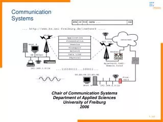
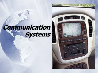
Source–journey–detector A useful model when describing communication systems based on: • visible light • infrared • microwaves • radio waves
Fibre optic systems use light A simple transmitter: button cell & LED A simple detector: phototransistor + multimeter Infrared light is used more commonly than visible light - less attenuation and dispersion.
Constructing optical fibres Two kinds of fibre are used. long distances within a building
SEP Optical transmission set schematic diagram
Total internal reflection In general, when passing from one medium (refractive index n1) to another medium (refractive index n2), (Snell’s law) At the critical angle, In optical fibres, the cladding material typically has a refractive index ~1% lower than that of the core, so critical angle is ~82o
Wireless communication … use microwaves and radio waves Demonstration: Creating a radio wave
Amplitude modulation A radio frequency (r.f.) carrier wave of fixed amplitude is generated. Itsamplitudevaries once an audio frequency (a.f.) signal is added.
Making a simple radio receiver A: AM modulated radio wave B: After diode rectification C: The r.f. wave is filtered out, leaving a.f. signal
Amplitude modulation Modulating the amplitude of a carrier wave
Frequency modulation A radio frequency (r.f.) carrier wave of fixed amplitude is generated. Its frequency varies once an a.f. signal is added.
Frequency modulation Modulating the frequency of a carrier wave SKE Physics 17
Digital encoding (pulse code modulation, PCM) Digital encoding of a carrier wave
Digital encoding close-up of part of the previous image
Analogue to digital encoding analogue signal sampling and encoding the analogue signal. Digitised values are in binary form, so the resolution is expressed in bits. 8 bits encode an analogue value as one of 256 different levels (28 = 256).
Digital to analogue decoding Sampling rate too low Resolution too low Encoding requires a sufficiently high sampling rate & resolution.
UK frequency allocations http://sitefinder.ofcom.org.uk/search Transmitter locations, with this additional information: • name of operator • station type • height of antenna • frequency range • transmitter power • Maximum licensed power • type of transmission (usually GSM)
Spectrum analysis Any waveform can be accurately represented as a sum of sine waves, each with its own frequency. If some of the frequencies are lost, then so is some of the information in the signal.
Bandwidth Each kind of signal contains a range of frequencies. The higher the data rate, the larger the bandwidth and the higher the frequency band needed. Bandwidth costs money: e.g. monthly charges for your mobile phone and Internet services