Download
1 / 52
530 likes | 729 Views
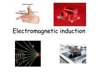
You just have to keep motion between the magnets and wires. Electromagnetic Induction. Magnetism can induce electrical currents in wires. Michael Faraday. 1791 – 1867 Great experimental scientist Invented electric motor, generator and transformers Discovered electromagnetic induction

E N D
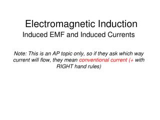
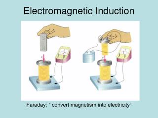
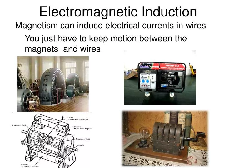
You just have to keep motion between the magnets and wires Electromagnetic Induction Magnetism can induce electrical currents in wires
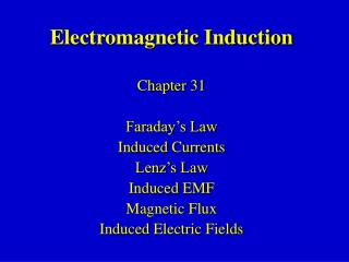
Michael Faraday • 1791 – 1867 • Great experimental scientist • Invented electric motor, generator and transformers • Discovered electromagnetic induction • Discovered laws of electrolysis Section 20.1
Faraday’s Experiment – Set Up • A current can be produced by a changing magnetic field. • First shown in an experiment by Michael Faraday • A primary coil is connected to a battery. • A secondary coil is connected to an ammeter. Section 20.1
Faraday’s Experiment • There is no battery in the • secondary circuit. • When the switch is closed, the ammeter reads a current and then returns to zero. • When the switch is opened, the ammeter reads a current in the opposite direction and then returns to zero. • When there is a steady current in the primary circuit, the ammeter reads zero. Section 20.1
Faraday’s Conclusions • An electrical current is produced by a changing magnetic field. • The secondary circuit acts as if a source of electromotive force (emf) were connected to it for a short time. • It is customary to say that an induced emf is produced in the secondary circuit by the changing magnetic field. • EMF is another word for VOLTAGE Section 20.1
When there is no relative motion between the coils of wire and the magnet there is no current produced
Current is created in the coil when the magnet is moved towards the coil. The current’s direction always opposes the change in the magnetic field Note: here conventional current (+) with RIGHT hand rule is used. The same result for electron flow would come from the left hand rule.
Current also exists when you pull it away from the coil, just in the opposite direction. The current in the coil is called an induced current. The coil itself acts as a source of emf known as induced emf.
Another way to look at it. Changing the area of a coil, in effect, reduces/increases the B field that the coil is subject to. Changing the B field strength experienced by the coil. This will also create a current.
Motional EMF The EMF Induced in a Moving Conductor
A rod is being pushed to the right with constant speed v. Suddenly the bulb lights. Why? Where is the current coming from ? Where is this opposing force coming from?
We have been using the term emf, ε, or electro motive force. ε=BLv Potential Difference
Magnetic Flux Motional EMF and Magnetic Flux
By definition therefore Of course the angle with the field is important
It is convenient express emf in terms of area when using induction in motors and generators. E = v BL can be rearranged below to create a new formula: since
Faradays Law actually reads Where N is the # of turns in the coil. But what is the negative all about?
Consider the field created by the counterclockjwise loop in our previous problem. What is the direction of its field?
The induced emf resulting from a changing magnetic field will produce a current in such a way that the induced magnetic field will oppose the original change in flux. Like “magnetic inertia”
We need ALTERNATING CURRENT to make this work. It creates a constantly ___________ing magnetic field Basically, this is a transformer!
Generators • Alternating Current (AC) generator • Converts mechanical energy to electrical energy • Consists of a wire loop rotated by some external means • There are a variety of sources that can supply the energy to rotate the loop. • These may include falling water, heat by burning coal to produce steam Section 20.4
AC Generators, Cont. • Basic operation of the generator • As the loop rotates, the magnetic flux through it changes with time. • This induces an emf and a current in the external circuit. • The ends of the loop are connected to slip rings that rotate with the loop. • Connections to the external circuit are made by stationary brushes in contact with the slip rings. Section 20.4
AC Generators, Final • The emf generated by the rotating loop can be found by ε =2 B ℓ v=2 Bℓ sin θ • If the loop rotates with a constant angular speed, ω, and N turns ε = N B A ω sin ω t • ε = εmax when loop is parallel to the field • ε = 0 when the loop is perpendicular to the field Section 20.4
AC Generators – Detail of Rotating Loop • The magnetic force on the charges in the wires AB and CD is perpendicular to the length of the wires. • An emf is generated in wires BC and AD. • The emf produced in each of these wires is ε= B ℓ v= Bℓ sin θ Section 20.4
DC Generators • Components are essentially the same as that of an ac generator • The major difference is the contacts to the rotating loop are made by a split ring, or commutator Section 20.4
DC Generators, Cont. • The output voltage always has the same polarity. • The current is a pulsing current. • To produce a steady current, many loops and commutators around the axis of rotation are used. • The multiple outputs are superimposed and the output is almost free of fluctuations. Section 20.4
Motors • Motors are devices that convert electrical energy into mechanical energy. • A motor is a generator run in reverse. • A motor can perform useful mechanical work when a shaft connected to its rotating coil is attached to some external device. Section 20.4
Motors and Back emf • The phrase back emf is used for an emf that tends to reduce the applied current. • When a motor is turned on, there is no back emf initially. • The current is very large because it is limited only by the resistance of the coil. Section 20.4
Motors and Back emf, Cont. • As the coil begins to rotate, the induced back emf opposes the applied voltage. • The current in the coil is reduced. • The power requirements for starting a motor and for running it under heavy loads are greater than those for running the motor under average loads. Section 20.4
Self-inductance • Self-inductance occurs when the changing flux through a circuit arises from the circuit itself. • As the current increases, the magnetic flux through a loop due to this current also increases. • The increasing flux induces an emf that opposes the change in magnetic flux. • As the magnitude of the current increases, the rate of increase lessens and the induced emf decreases. • This decreasing emf results in a gradual increase of the current. Section 20.5
Self-inductance, Cont. • The self-induced emf must be proportional to the time rate of change of the current. • L is a proportionality constant called the inductance of the device. • The negative sign indicates that a changing current induces an emf in opposition to that change. Section 20.5
Self-inductance, Final • The inductance of a coil depends on geometric factors. • The SI unit of self-inductance is the Henry • 1 H = 1 (V · s) / A • You can determine an expression for L Section 20.5
Joseph Henry • 1797 – 1878 • First director of the Smithsonian • First president of the Academy of Natural Science • First to produce an electric current with a magnetic field • Improved the design of the electro-magnet and constructed a motor • Discovered self-inductance Section 20.5
Inductor in a Circuit • Inductance can be interpreted as a measure of opposition to the rate of change in the current. • Remember resistance R is a measure of opposition to the current. • As a circuit is completed, the current begins to increase, but the inductor produces an emf that opposes the increasing current. • Therefore, the current doesn’t change from 0 to its maximum instantaneously. Section 20.6
RL Circuit • When the current reaches its maximum, the rate of change and the back emf are zero. • The time constant, , for an RL circuit is the time required for the current in the circuit to reach 63.2% of its final value. Section 20.6
RL Circuit, Graph • The current increases toward the maximum value of ε/R Section 20.6
RL Circuit, Cont. • The time constant depends on R and L. Section 20.6
Energy Stored in a Magnetic Field • The emf induced by an inductor prevents a battery from establishing an instantaneous current in a circuit. • The battery has to do work to produce a current. • This work can be thought of as energy stored by the inductor in its magnetic field. • PEL = ½ L I2 Section 20.7
Many devices we plug in don’t need 120 Volts to run. A transformer can change the voltage.It only works with AC current.
Under the cover • This transformer came with a rechargeable electric screwdriver. This particular transformer is rated at 3 volts and 240 milliamps.
What you can see here are two windings. The purpose of a transformer is to convert one AC voltage to another AC voltage. In this case the transformer converts the normal 120 volt AC current in your house down to three volts.
Primary Winding • The 120 volts comes in on the primary winding on the left. Running down the middle of that winding (as well as around the outside) is an iron core. The AC current in the primary winding creates an alternating magnetic field in the iron just as it would in an electromagnet. Iron Core
Secondary Winding • The other winding, known as the secondary winding wraps around the same iron core. In the secondary winding the magnetic field in the core creates current. The voltage in the secondary is controlled by the ratio of the number of turns in the two windings. So ifthe primary and secondarywindings have the same number of turns, the primary and secondary voltage will be the same. If the secondary winding has half as many turns as the primary then the voltage in the secondarywill be half that of the voltage in the primary.
You can see in the following figure that the primary in this particular transformer uses very fine wire while the secondary uses much thicker wire. To drop down to 3 volts, there needs to be 40 times more turns in the primary than in the secondary.
On the other side of the transformer you find two diodes wrapped in rubber insulation. The diodes act as a rectifier, turning the AC current into DC current. Most transformer cubes that you find around the house produce a low-voltage DC current (3 to 12 volts, and less than an amp of current).